8
1
2
3
Installation instructions
Frame type and serial number
The name plate is located at the head
end on the left longitudinal beam below
the raised head.
Supplied accessories
Installation accessories: mattress holder
(foot end), 4 non-slip foils
Connection accessories:
mains adapter, lead cable, control box,
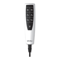
cable hand switch (x82),
radio remote control (x83 und x84)
Placing in a bed
Please heed the necessary space for the
adjustable frame parts, e.g. in rooms
with inclined roofs, superstructures over
the bed or padded head sections. An
installation depth of approx. 14 cm (floor
clearance) is needed in the substructure
for the adjustment mechanism and drive
system.
Please always heed the spacing of the
back part with its motorised adjustment,
to the head part of the bed. There should
be spacing of at least 1.5 cm here
when the bed is laid flat. To rule out any
unintentional slipping, please screw the
frame to the bed at the pre-drilled points
in the metal substructure.
Side support sections must not exceed
4 cm in width (middle frame 8 cm). The
motor frame must always fit in the bed
without any tension. For beds with trian-
gular supports (leg length max. 15 cm),
please use the „Extension elements“ in-
stallation kit (available as accessory). For
a stable bed structure, we always recom-
mend a supporting point in the middle of
the bed for triangular supports.
Non-slip foil
Affix in the bed structure to the supporting
point of the frame. The foils prevent any noi-
se that could be caused by the frame slipping
in the bed structure.
Mattress holder
Attach the supplied holder at the foot end.
The plastic clamps are premounted.
2-Motorer (x82)
mit Kabelhandschalter
Please proceed as follows to
commission your motor frame:
1 Transport protection: Remove the
Velcro
®
fastenings and the card-
boards under the frame.
2
Hinge up the foot part of the frame,
access to the black fabric pocket
3
Unpack control box and power
adapter.
4
Connect motor frame to mains.
5
Control box can be pushed onto the
thigh motor at the side.
Adjust motor frame with cable hand
switch.
Connection and commissioning
 Loading...