10
3.2 SETUP OF THE ULTRACOOL UNIT (UC 8 TO UC 65)
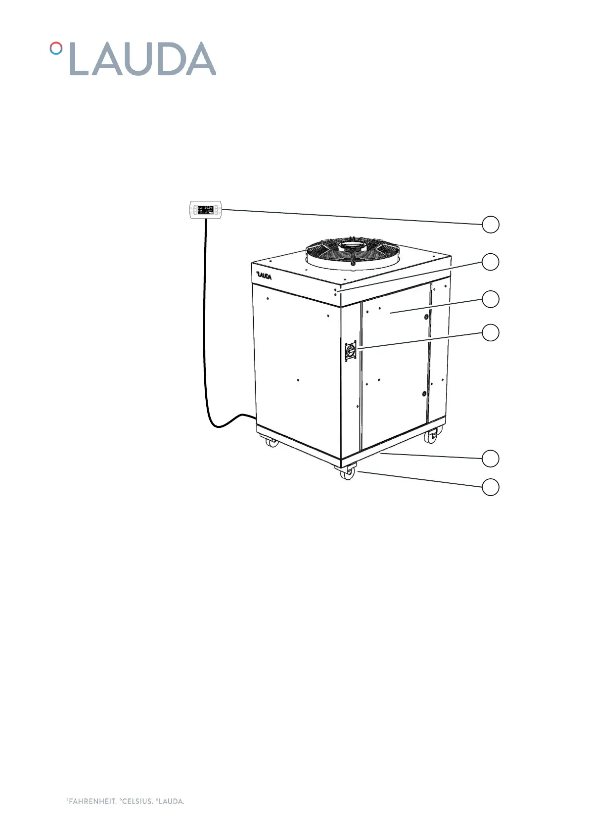
Front of the UC 24
1. External controller display
2. Status and Warning/Alarm LEDs
3. Right panel. It gives access to the electrical box
4. Main power switch
5. Power and communications cables inlet (below the unit)
6. Four wheels with locking brake (feet on UC 50 and UC 65)