16
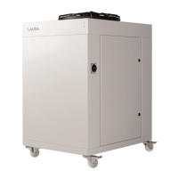
Introduce the main power supply cable through the cable gland located on the base of the chiller and connect
it to the incoming power terminals which are located on the left side of the X1 terminal block inside the
electrical box of the chiller:
For the electrical supply of the Ultracool unit, use an appropriate electrical line according to the data in the
characteristics plate.
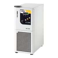
Take the cable for the external controller display out of the chiller through the brush gland on the base of the
chiller and connect it to the back of the display.
Note: The external controller display has no IP protection; make sure it is installed on a location protected
from the weather, from dust and from any water splashes.
If the chiller is controlled remotely, it is also possible to remove the display after the initial configuration and
store it in a safe location, as the chiller does not need it to operate. In such a case the end connector of the
display’s cable also needs to remain protected from the elements, for example keeping it inside the electrical
box of the chiller.
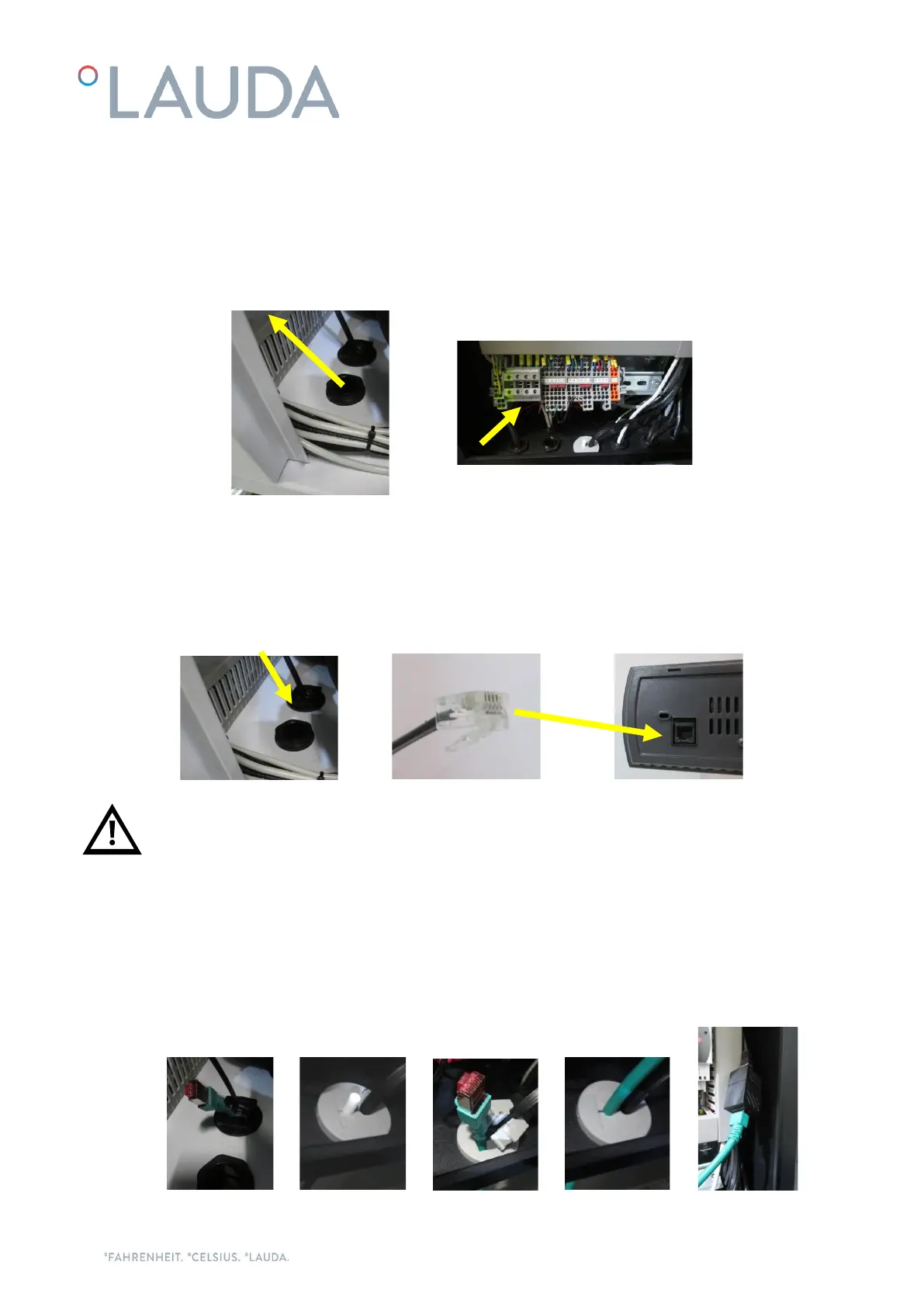
Ethernet cable connection, if the chiller is connected to a local network via Ethernet or to a Cloud gateway:
Introduce the Ethernet cable through the brush gland on the base of the chiller and into the electrical box
through the rubber cable holder, then connect it to the Ethernet connector: