8
3 ULTRACOOL UNIT DESCRIPTION
3.1 SETUP OF THE ULTRACOOL UNIT (UC 2 AND UC 4)
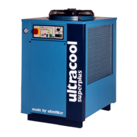
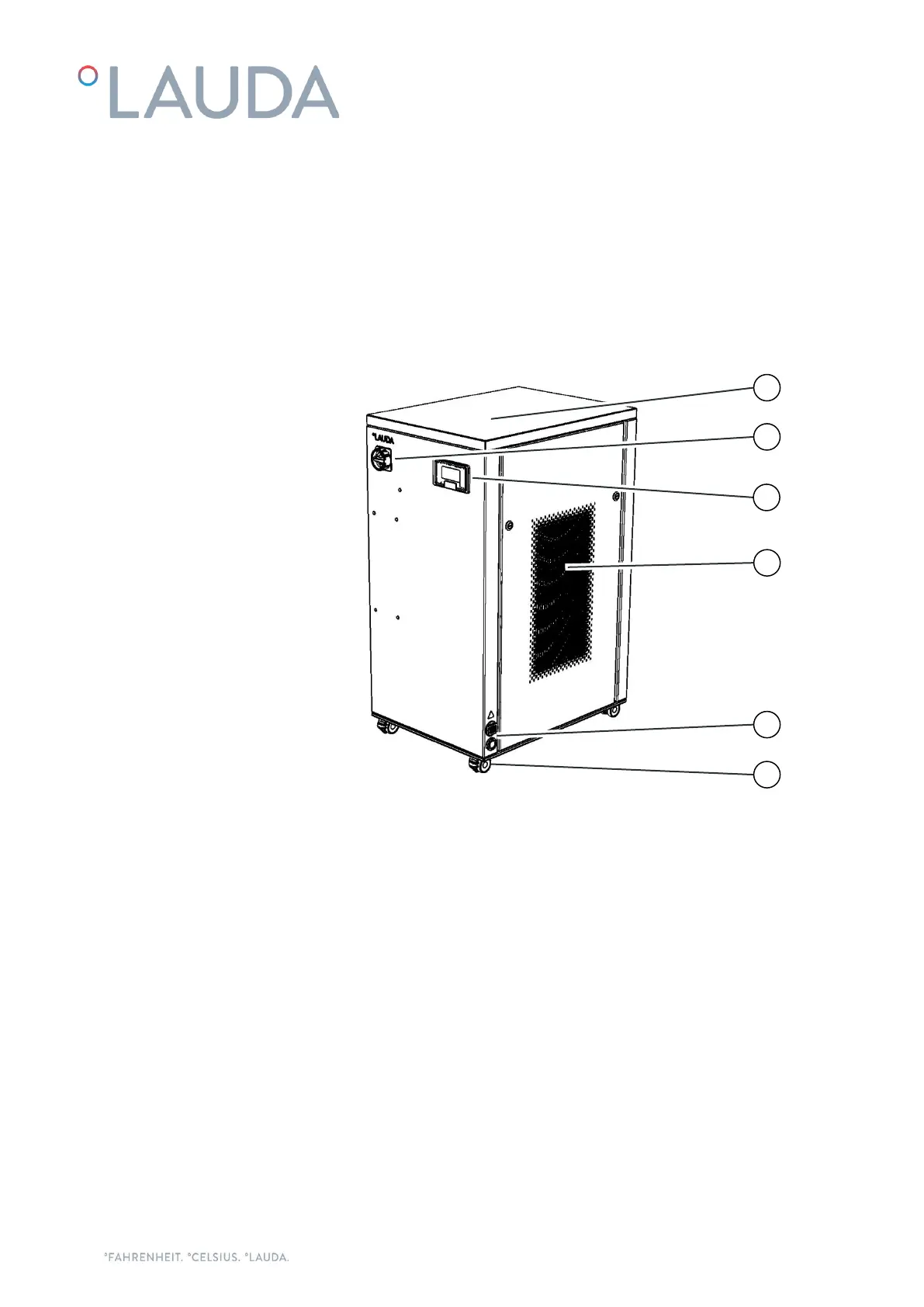
Front of the UC 4
1. Top panel. It gives access to the electrical box.
2. Main power switch.
3. Controller.
4. Ventilation grid (on both sides, warm air exhaust).
5. Power and communications cables inlet.
6. Four wheels with locking brake.