Launch TLT235、TLT240 Economical Two-post User’s Manual
10
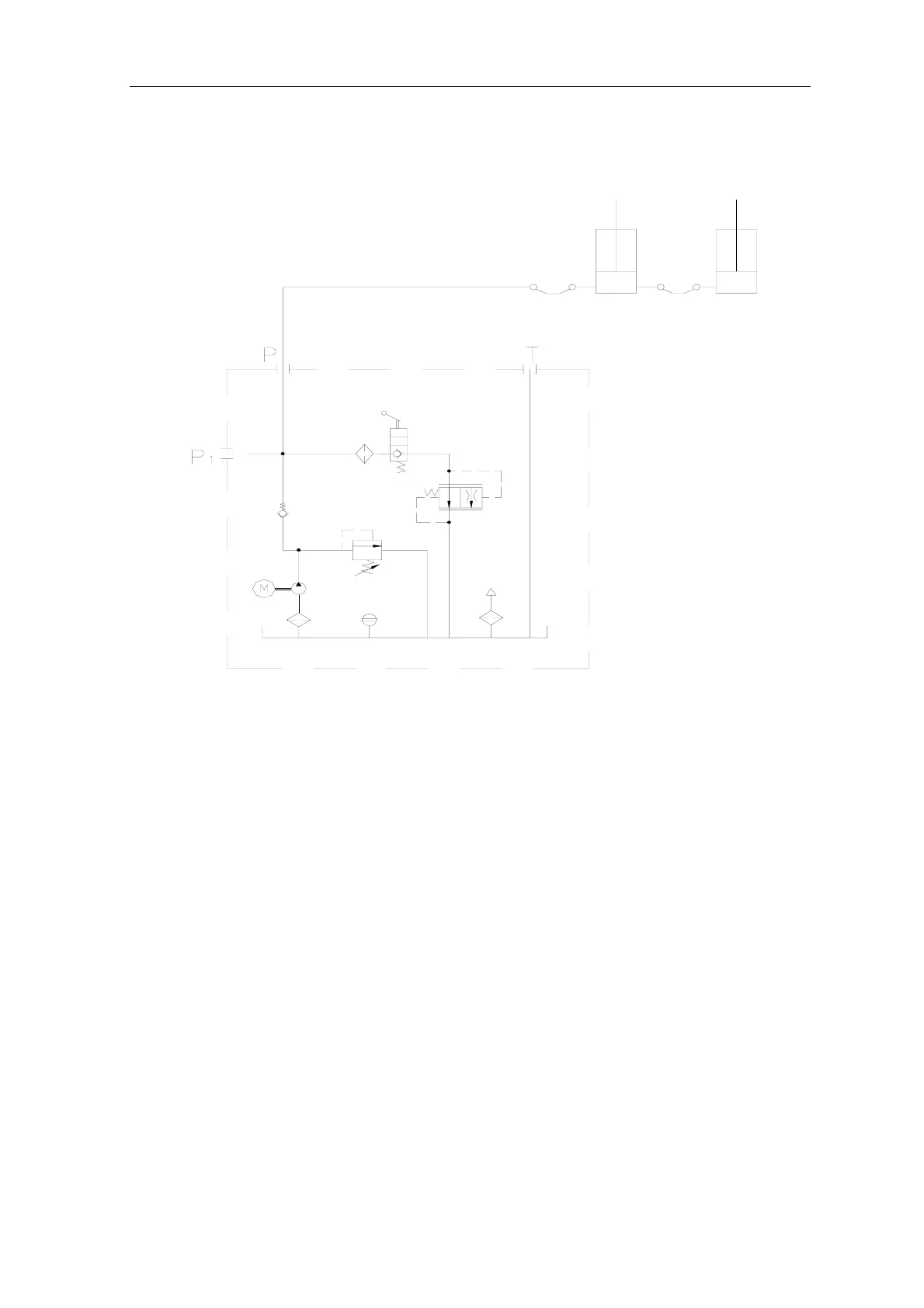
Diagram of the hydraulic system of floor-plate 2-post lift
2
3
1
4
5
7
6
8
8
9
9
10
11
Fig.4b
1- Gear pump, 2- Motor, 3- Oil filter, 4- Check-valve, 5- Safety valve, 6- Lowering handle valve,
7- Servo flow-control valve, 8- Hose, 9- Hydraulic cylinder, 10- Level gauge, 11- Air filter
The working principle of the hydraulic system is as
follows:
As shown in Fig.4b, when the start button is pressed, the
motor 2 is started, driving the oil pump 1 , sucking the
hydraulic oil from the oil tank into the oil cylinder 9, forcing
the piston rod move. At this time, the safety valve 5 is
closed.( the Max working pressure is already adjusted
before ex-factory. The safety valve can ensure the capacity
of the rated load, but when the pressure in the system
exceeds the limit, automatically overflow will be happened
inside safety valve to protect the hydraulic system).
Release the start button to stop the oil supply and the lifting
will stop. For lowering, first start Motor 2 to raise vehicle of
5~10mm, pull the steel ropes on two carriages to release
the safety lock mechanism, then press the lowering handle,
the valve 6 is actuated, the hydraulic oil flows back and the
lift starts lowering.