LAUNCH Electronic Two-post User’
28
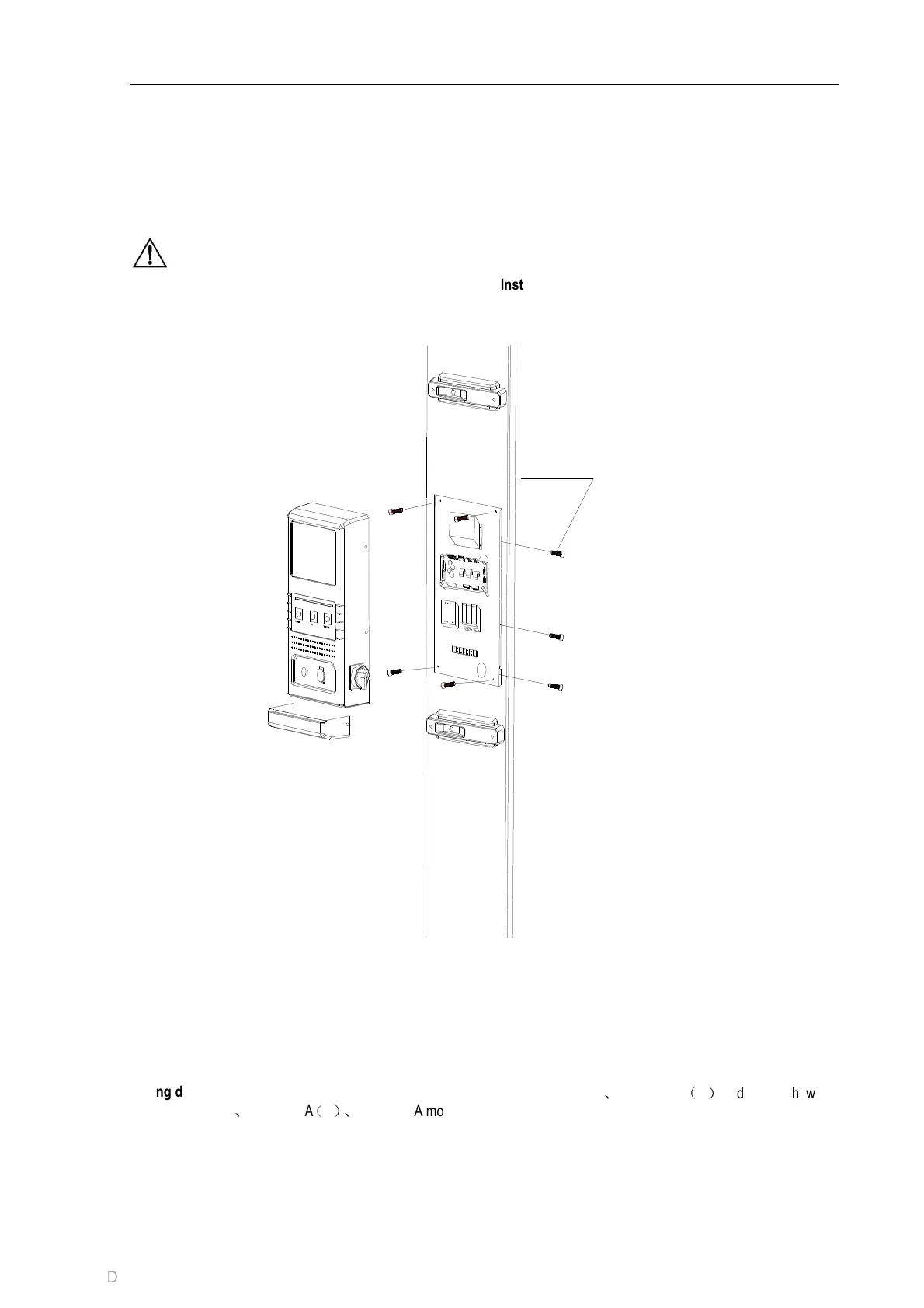
10.2.9 Install the electric control box
Use M5x12 Screw and washer to fix the electric
control box casing onto the column.(Fig.12)
Connect the electrical wiring as shown in Fig. 12.
Install the bottom case of the electric control box.
Note:
This equipment needs NFB (non-fuse breaker) upon
installation. This equipment does not include it. It
should be bought and installed by users. The NFB is
16A.
The power cable is required to be greater
than 2.5mm
2.
Coat the roller and carriage passage with the
lubrication grease. Raise and lower the carriages
twice without load t o see if they work well.
After the column is fixed, operate with load
Installation schematic diagram of electric control box
Fig 12
Wiring diagram
TLT235SBA
、
TLT235SBA
(
E
)、
TLT240SBA models
are shown in Fig13a.
TLT240SCA
、
TLT235SCA
(
U
)
models are shown in
Fig13b.
M4*6 Screw
(C) Diagtools; www.diagtools.eu; diagtools@diagtools.lv; Pernavas 43A, Riga, Latvia, LV-1009; +37129416069