LAUNCH Electronic Two-post User’
18
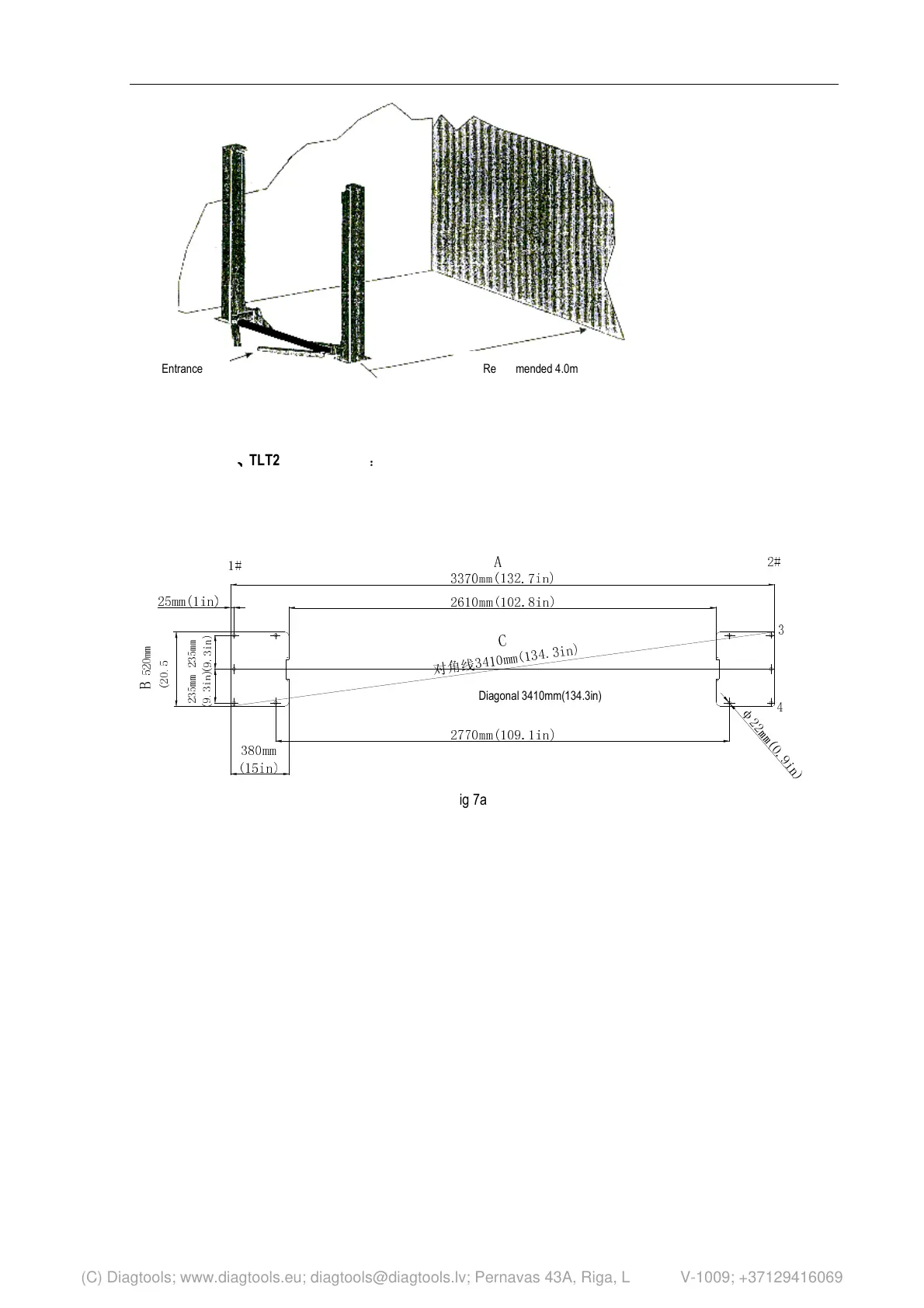
Fig 6
10.2.2 Base plate layout
TLT235SBA
、
、、
、
TLT240SBA Models
:
With total width
(A) as the basis, draw two parallel lines (#1 and #2)
on the concrete slab, with the error within 3mm.
Determine the power side column location on any
chalk line, and mark the total width (B) of the base
plate. Mark the points 3 and 4. Starting from point 3,
draw one diagonal line (C) ,forming a triangle. In this
way, the vertical lines can determine the location of
the two columns.(as shown in 7a)
B
5
2
0
m
m
(
2
0
.
5
in)
2
3
5
m
m
(
9
.
3
i
n
)
1#
C
对
角
线
3
4
1
0
m
m
(
1
3
4
.
3
i
n
)
φ
2
2
m
m
(
0
.
9
i
n
)
4
3
2#
A
2610mm(102.8in)
2770mm(109.1in)
3370mm(132.7in)
2
3
5
m
m
(
9
.
3
i
n
)
380mm
(15in)
25mm(1in)
Fig 7a
Recommended 4.0m Entrance
Diagonal 3410mm(134.3in)
(C) Diagtools; www.diagtools.eu; diagtools@diagtools.lv; Pernavas 43A, Riga, Latvia, LV-1009; +37129416069