LAUNCH X-631/X-631+ Installation and Parts Manual Structure
4
Structure
Overall Structure
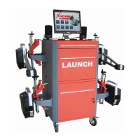
The X-631/X-631+ wheel aligner mainly consists of main unit, probe rods, wheel clamps, turntables, steering wheel holder
and brake pedal depressor, etc. as shown in the Fig.3.1.
Fig.3.1
1— main unit, 2—RL probe rod assembly, 3—FL probe rod assembly, 4—FR probe rod assembly, 5—RR probe rod
assembly, 6—wheel clamps, 7—turn tables, 8—steering wheel holder, 9—brake pedal depressor, 10---wheel clamp tie
 Loading...