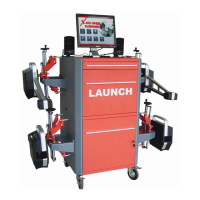
LAUNCH X-631/X-631+ Installation and Parts Manual Structure
7
When using the electronic turn table, connect its connecting cable to 3PIN socket in the middle of the front left or front right
probe rod.
Steering Wheel Holder
X-631/X-631+ has a steering wheel holder as shown in Fig.3.7. Use the steering wheel holder to lock the steering wheel
according to the tips on the screen.
Fig.3.7 Steering wheel holder
Brake Pedal Depressor
X-631/X-631+ has a brake pedal depressor as shown in Fig.3.8. It is used to hold the brake pedal down.
Fig.3.8 Brake pedal depressor
Calibrating Frame and its Converter Connector (Optional)
They are mainly used to calibrate the probe rod system of X-631/X-631+ wheel aligner.
Fig.3.9 Calibrating frame and its converter connector
 Loading...