Important: Nev er tr y to br ush dir t fr om
the paper filter; br ushing will f orce dir t into
the fiber s. R eplace the paper element if it is
dama ged or cannot be cleaned thor oughl y .
2. Carefully clean the r ubber seal on the paper
filter to prev ent debris from entering the
engine .
3. Inspect the filter for tears , an oily film, and
damag e to the r ubber seal. R e place if necessar y .
Installing the Foam and Paper
Elements
Important: T o pr ev ent engine dama ge,
al w ays operate the engine with the complete
f oam and paper air cleaner assembl y installed.
1. Install the g rid o v er the paper element and
install the assembly into the air cleaner base
( Figure 19 ).
Note: Mak e sure that the r ubber seal is flat
ag ainst the air cleaner base .
2. Install the foam element o v er the g rid
( Figure 19 ). T he g rid m ust be placed betw een
the foam element and paper element to prev ent
oil from contaminating the paper element.
3. Install the air cleaner co v er o v er the filter . Use
the co v er knobs to secure the co v er in place
( Figure 19 ).
Servicing the Engine Oil
Chec k the oil lev el before eac h use or after ev er y
8 hours .
Chang e the oil after the first 20 operating hours
and ev er y 100 operating hours thereafter .
Oil T ype: Deterg ent oil (API ser vice SJ or higher)
Crankcase Capacity:
• 0.95 qt (0.9 l) when the filter is not changed ;
• 1.11 qt (1.05 l) when the filter is changed
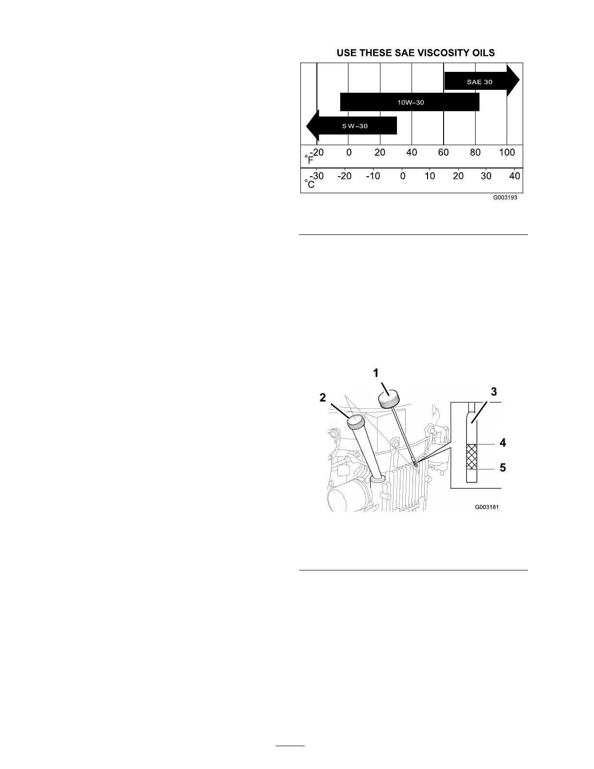
Viscosity: 10W -30 is recommended for g eneral
use . Other viscosities sho wn in the c har t belo w
ma y be used when the a v erag e temperature in
y ou area is within the indicated rang e .
Figure 23
Checking the Oil Level
1. P ark the mac hine on a lev el surface , diseng ag e
the blade control switc h, stop the engine , and
remo v e the k ey .
2. Clean around the oil dipstic k ( Figure 24 ) so
that dir t cannot fall into the fill hole and
damag e the engine .
Figure 24
1. Oil dipstick 4. Full
2. Filler tube 5. Add
3. Dipstick end
3. Unscrew the oil dipstic k and wipe the end
clean ( Figure 24 ).
4. Inser t oil dipstic k fully onto the fill hole , but
do not screw it in.
5. Pull the dipstic k out, and look at the end. If
the oil lev el is near or belo w the lo w er limit
mark, slo wly pour only enough oil into the fill
hole to raise the lev el to the upper limit mark
on the dipstic k. Do not o v erfill. ( Figure 24 ).
22
 Loading...