13
To remove the shaft:
■ Stop the engine and remove the battery pack.
■ Loosen the locking collar by turning counter-clockwise, and pull away from the connection sleeve.
■ Pull out the shaft to remove.
WARNING
Never adjust the assist handle while the trimmer head is running. Failure to stop the engine may cause
serious personal injury.
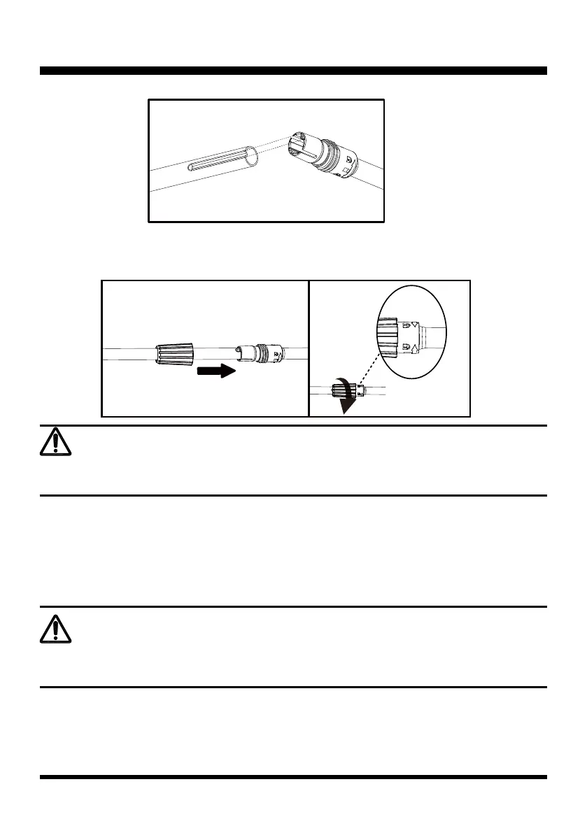
■ Slide the shaft into the shaft connection sleeve, then slide the locking collar onto the connection sleeve to
lock into place (Fig. 5).
■ Secure the shaft by turning the locking collar clockwise (Fig. 6).
ASSEMBLY
WARNING
Ensure that the locking collar is fully tightened before operating the tool; check it periodically for
tightness during use to avoid serious personal injury.
INSTALLING AND ADJUSTING THE ASSIST HANDLE (See Figs. 7-10)
■ Loosen and remove the screw bolt and wing nut.
■ Fix the assist handle onto the shaft as shown by rmly pushing the handle onto the shaft. Make sure that
the groove side faces the engine (Fig. 7).
■ Adjust the assist handle to your desired position. The assist handle can only be moved in the direction
between the arrow marked "Handle Position" and shaft connection sleeve (Fig. 8).
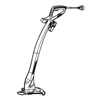
Fig. 4
Fig. 5 Fig. 6
 Loading...