36
NOPULL
TM
STARTER SYSTEM
F. If the battery indicator LED does not turn on, the possible causes are as below:
1). The microswitch is broken. Replace it.
2). The wiring harness of the microswitch has detached. Re-weld it.
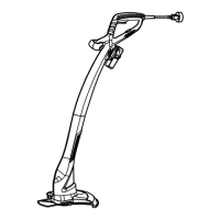
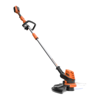
3). There is failed contact in the battery connector to the PCB. Adjust the battery connector (Fig.
71).
4). Battery breaks down without voltage output. Use a multimeter to test if an open circuit occurs in
the fuse of the battery. If yes, replace it (Fig. 72).
Ŷ7KHHOHFWULFPRWRUVWDUWVWKHQVWRSVZKHQSUHVVLQJWKHVWDUWEXWWRQ$FFRUGLQJWR/('LQGLFWRUVWKH
possible causes are as below:
$,IWKHUHLVQR/('ÀDVKLQJWKHVWDUWEXWWRQPD\KDYHEURNHQRULIWKHVWDUWEXWWRQUHPDLQVSUHVVHG
for 5 seconds, the motor will stop automatically).
%*UHHQÀDVKLQJRIWKHEDWWHU\LQGLFDWRU/('LQGLFDWHVDVKRUWFLUFXLWLQWKHHOHFWULFVWDUWHU&KHFNWKH
electric motor and the motor drive lines as illustrated above.
&$OWHUQDWHUHGDQGJUHHQÀDVKLQJRIWKHEDWWHU\LQGLFDWRU/('LQGLFDWHVDQRYHUFXUUHQWLQWKHHOHFWULF
starter. Check if the engine is stuck and cannot be rotated smoothly.
Ŷ7KHHOHFWULFPRWRUVWDUWVQRUPDOO\EXWWKH/('GRHVQRWWXUQRQZKHQSUHVVLQJWKHVWDUWEXWWRQ
Possible causes are:
$7KHUHLVORRVHRUIDLOHGFRQWDFWRUIDOORIILQWKHFRQQHFWLRQRI3&%RU/('SDQHOWRWKHÀDWFDEOH
B. LED panel is broken.
Ŷ7KHHQJLQHFDQQRWEHVWRSSHGZKHQSUHVVLQJWKHVWRSVZLWFK7KHSRVVLEOHFDXVHVPD\EHWKDWWKH
stop switch has failed or the wiring harness of the stop switch has broken. Check as below:
Open the corrugated pipe buckle, disconnect the male and female terminals of the stop switch wiring
harness (covered by two transparent insulation covering):
A. Press the stop switch, test the stop switch wiring harness of the handle part using the resistance
stall of multimeter (Fig. 73). If conduction fails, the possible causes are:
1). The wiring harness of the handle has detached from their welding position to the stop switch;
2). There is loose or failed contact in the connection of the wiring harness of the handle part to the
Fig. 72Fig. 71
Microswitch
Battery Connector
Fuse

 Loading...