MCCB
ACL
BR
R/L1
X
U
YV
Z
W
S/L2
T/L3
FB
FC
U/T1
V/T2
IM
Br
W/T3
OFF
FU
ON
MC
R
F
R
F
FX
FR
RR
DFL
RST
COM
RX
BX
F
R
MC
F
FX
R
RX
BX
BR
MC
MC
+
FM
FRQ
COM
−
+V
VRF
COM
HF-320α
P
P1
(+)
RC
RY
Power
Preparation
for operation
Stop
Normal
rotation
Reverse
rotation
Note 2
Note 3
Reset
Frequency
counter
10V F.S.
Tx
Note 1
Speed setter
1kΩ
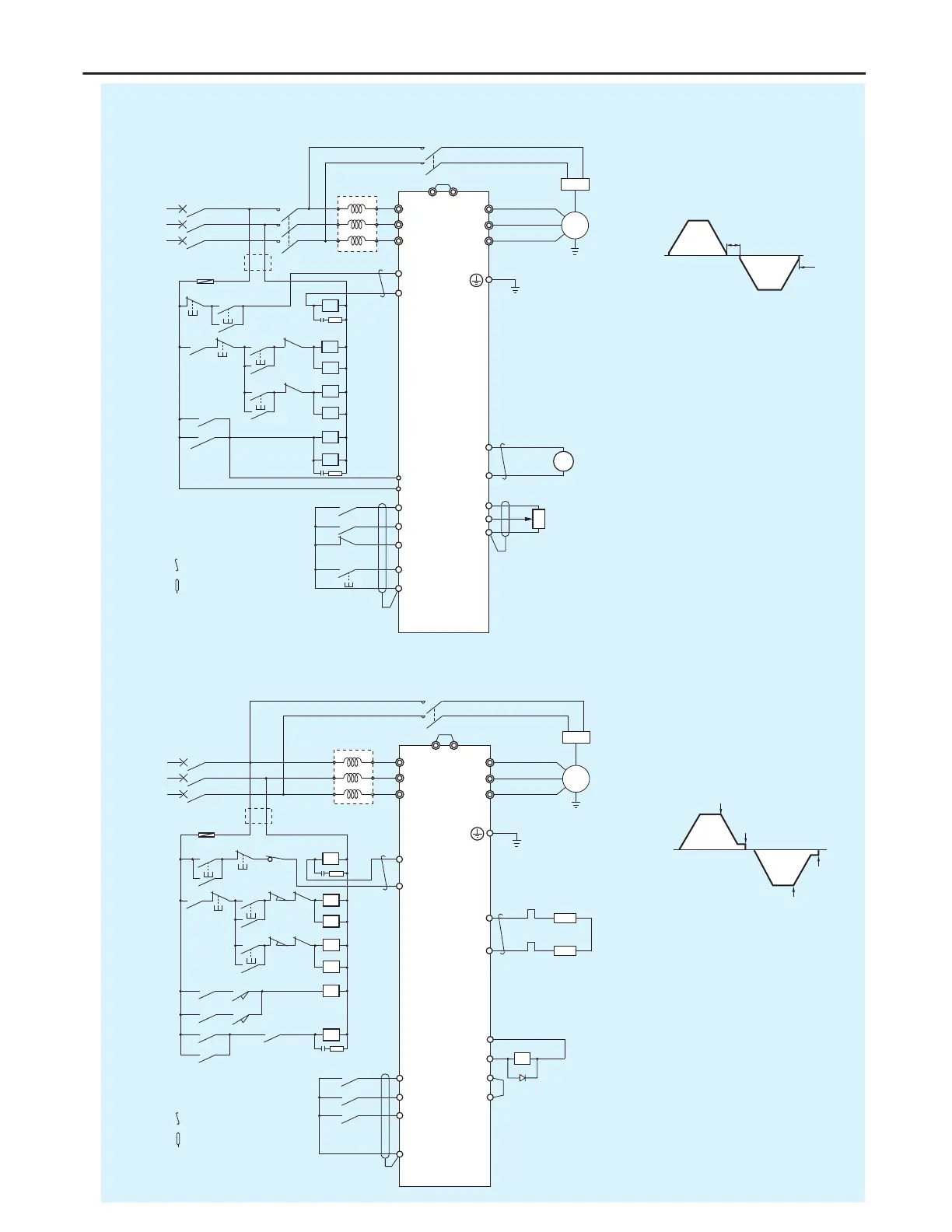
Note 1: When the power supply is a 400
V class, install a step-down
transformer.
Note 2: Set parameter F114 to 54.
Note 3: Set parameter F130 to 14.
: Twisted wire
: Shielded wire
Brake
Brake
Normal
rotation
Reverse
rotation
Operation pattern
MCCB
ACL
BR
XU
YV
Z
W
FB
FC
IM
Br
P
PR
FU
R
LS2
LS4
F
R
F
FX
FR
RR
DFL
COM
RX
DF
F
LS1
R
F
R
LS3
F
FX
R
RX
DF
BR
Tx
LS1
HF-320α
LS2
L
S1, LS3
LS3
LS4
P P1
THR
MC
MC
ON
MC
OFF
THR
UPF
R/L1
S/L2
T/L3
U/T1
V/T2
W/T3
(+)
(+)
Power
Note 1
Stop
Normal
rotation
Reverse
rotation
Note 2
Note 4
Tx
Note 3
: Twisted wire
: Shielded wire
Normal
rotation
Normal
rotation
Operation pattern
Braking resistor
The limit switch is a
holding type.
Preparation
for operation
Note 1: Use inflammable cable for
braking resistor wiring.
Note 2: Parameter Sr1 is for
slow-speed frequency setting
and FC is for high-speed
setting.
Note 3: When the power supply is a
400 V class, install a
step-down transformer.
Note 4: Set parameter F131 to 4 and
adjust the braking timing by
F100 .Parameters F100
should be set at approx. 2 Hz
usually.
P24V
OM
DRV
COM
UPF

 Loading...