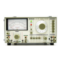
The Leader LBO-522 and LBO-523 are portable dual-trace oscilloscopes designed for a wide range of applications in production and service areas, including measurements and testing of TV sets, VTRs, and computer peripheral equipment. These oscilloscopes feature TV synchronization separators, variable hold-off, and V-AXIS magnifier functions.
Function Description
The LBO-522 and LBO-523 oscilloscopes are primarily used for displaying and analyzing electrical signals. They allow users to visualize waveforms, measure voltage, time intervals, and frequency, and observe phase differences between two signals. The dual-trace capability enables simultaneous display of two input signals, facilitating comparison and analysis. The instruments support various display modes, including CH-1, CH-2, CHOP, ALT, and ADD, offering flexibility for different measurement scenarios.
Important Technical Specifications
CRT Display:
- Type: 150 mm Rectangular, Internal-graticule Scale, [Aluminized Screen] and Flat Face with illumination lamps and Percentage scale.
- Accelerating Potential: 7 kV/2 kV regulated.
- Effective Display Area: 8 x 10 div. (1 div. = 10mm).
- Beam Rotator: Adjustment on front panel.
- Graticule Illumination: Continuously variable.
- Intensity Modulation: Blanked by TTL Level Signal.
Vertical Amplifiers (CH-1 and CH-2):
- Sensitivity: 5 mV/div. to 5V/div. (all bandwidth), 0.5 mV/div. to 2 mV/div. (5 MHz: MAG x 10) with variable in 10 steps, 1-2-5 sequence, continuously variable between steps.
- Calibration Accuracy: ±3% (±5%: MAG x 10).
- Bandwidth (-3 dB, 8 div.):
- DC coupled: DC to 20[35] MHz (DC to 5 MHz: MAG x 10).
- AC coupled: 10 Hz to 20 [35] MHz.
- Rise Time: 17.5[10] ns (70 ns; MAG x 10).
- Input Impedance: 1 MΩ ± 1.5%, 30 pF within ± 5 pF (Tolerance: within ± 2 pF).
- Input Coupling: AC, GND, DC.
- Maximum Input: 600V (DC + ACp-p).
- Display Modes: CH-1, CH-2, CHOP, ALT, ADD.
- Polarity Invert: CH-2 INVERT.
- CH-1 Output: Approx. 0.1V/div. into 50Ω (DC to 20[35] MHz, -3 dB).
Horizontal Amplifier:
- Sweep Method: Trigger sweep and Automatic trigger sweep.
- Sweep Time: 0.2 µs/div. to 0.2 s/div., 1-2-5 sequence 19 steps with continuous adjuster.
- Calibration Accuracy: ±3%.
- Hold-off Variable: One sweep or more.
- Magnifier: 5[10] times ±5%.
- Max. Sweep Time: 40[20] ns/div. (MAG x 5[10] ON).
Synchronization:
- Signal Sources: ALT, CH-1, CH-2, LINE, EXT.
- Coupling: AC, HF-REJ, TV-V, TV-H.
- Slope: + or –.
- Sensitivity (NORM):
- 30 Hz – 10 MHz: 0.5 div. (INT.), 0.2Vp-p (EXT.).
- 2 Hz – 20[35] MHz: 1.5 div. (INT.), 0.6Vp-p (EXT.).
- Sensitivity (AUTO):
- 30 Hz – 10 MHz: 0.5 div. (INT.), 0.2Vp-p (EXT.).
- 30 Hz – 20[35] MHz: 1.5 div. (INT.), 0.6Vp-p (EXT.).
- TV Synchronization: Extracts synchronizing signal from composite video signal for stable synchronization. Slope switch selected according to polarity of video signals.
X-Y Mode (X=CH-1, Y=CH-2):
- Sensitivity: X axis: 5 mV/div. to 5V/div.; Y axis: 5 mV/div. to 5V/div.
- X axis Bandwidth: DC or 10 Hz to 1 MHz (-3 dB, ref. 8 div.).
- X-Y Phase: Less than 3º at 100 kHz.
Calibrator:
- Output Voltage: 0.5Vp-p ±2%.
- Frequency: Approx. 1 kHz, square wave.
Power Requirements:
- Line Voltage: AC 100, 120, 200, 220, 240V 50/60 Hz.
- Power Consumption: 50W.
Size and Weight:
- Dimensions: 160(H) x 290(W) x 375(D) mm.
- Weight: 8.5 kg.
Supplied Accessories:
- Direct/Low capacitance probe LP-16AX (2)
- BNC terminal adapter (2)
- Time lag fuse (1)
- Instruction manual (1)
Optional Accessories:
- Protective front cover
- Accessories pouch
Usage Features
Power Source Voltage: The instrument can operate within ±10% variation of the rated voltage (100V, 120V, 200V, 220V, 240V). Incorrect voltage can damage the power supply. Fuse ratings vary by voltage.
Signal Input: Input signals higher than 600V (ACp-p + DC) may damage circuit components. Maximum allowable input voltage is 600V (ACp-p + DC) for vertical and external synchronization input terminals.
Magnetic Field Influence: Strong magnetic fields can cause waveform distortion or trace decline. Avoid using the instrument near high-power equipment or transformers.
Operating Environment: Designed for 0°C to ±40°C and 10% to 90% relative humidity. Operation in severe environments may shorten the instrument's life.
CRT Intensity: The CRT uses burn-resisting fluorescent material, but prolonged display of bright dots or traces at high intensity can cause damage. Maintain minimum necessary intensity and obscure focus when not actively observing.
Trans-less Equipment Connection: When connecting to trans-less equipment, which may have primary power line voltage on the chassis, use an isolation transformer (1:1 ratio) to prevent electric shock and damage to the device under test.
Probe Usage: The LP-16AX probe offers X1 and X10 switching.
- X10 Mode: Provides high resistance and low capacity, attenuating input voltage by 1/10. Requires adjustment of the probe's capacitor for flat square wave calibration.
- X1 Mode: Maintains high sensitivity but has a large input capacity (approx. 250pF), which must be considered for measurements.
- Straight Tip: Convenient for testing points on printed circuit boards; the retractive hook tip can be detached.
Ground Connection: Use the shortest possible shielded wire for ground connections, especially with probes, connecting to a ground point close to the signal source.
Dual Trace Measurement:
- ALT (Alternation): Displays CH-1 and CH-2 alternately sweep by sweep. Suitable for higher speed sweeps. Flicker may occur at low sweep speeds (<0.5 ms/div.).
- CHOP (Rapid Switching Display): Switches between CH-1 and CH-2 at high speed (approx. 250 kHz), displaying continuous waveforms. Ideal for slow speed sweeps. At higher speeds (>0.5 ms/div.), the trace may appear as a dotted line.
Synchronization to Waveforms:
- AUTO Synchronization: Automatically places the sweep circuit in free-run state when no trigger pulse is produced, displaying a horizontal trace. Suitable for waveforms with frequencies of 50 Hz or more.
- NORM Synchronization: Pull the LEVEL knob to NORM to remove waveforms when no input signal is applied or the trigger level is incorrect.
- SOURCE Selection: Internal signals (CH-1, CH-2, ALT, LINE) or external signals (EXT) can be selected for synchronization. ALT mode allows synchronization of two signals even without a synchronized relationship. LINE synchronization is useful for observing rectifier/filter circuits or TV sets with power non-synchronization.
- COUPLING Selection: AC coupling is generally used for stable synchronization over 2 Hz or higher bandwidth, eliminating DC components. HF REJ (High-Frequency Rejection) is used for signals with noise or parasitic oscillations above 100 kHz, filtering out high-frequency components. TV-V and TV-H modes automatically separate horizontal and vertical synchronization signals from composite video signals for stable display.
- SLOPE Selection: Selects positive (+) or negative (-) slope for triggered sweep based on the waveform's slope.
- LEVEL Adjustment: Adjusts the starting position of the triggered sweep. For simple, symmetrical signals, set to PRESET (notched position) for synchronization at the middle of the waveform.
- HOLDOFF (Variable Knob): Adjusts the pause time of the sweep, preventing triggering by unrequired pulses in intermittent pulse trains.
CH-1 Output Terminal: Provides the CH-1 input signal (approx. 0.1V/div. into 50Ω) for connection to a frequency counter or as a high-sensitivity, wideband amplifier.
Z Axis Input Terminal: Used for intensity modulation, applying 0V to +5V signals to intensify or erase parts of the trace line.
X-Y Mode (LBO-523 only): Grounding the center conductor of the REMOTE X-Y BNC terminal (while the TIME switch is not on X-Y) enables X-Y mode operation for remote control.
Maintenance Features
User Maintenance and Calibration:
- ROTATION Control: A screw adjuster on the front panel (9) is used to correct the tilt of the horizontal trace, which can be caused by terrestrial magnetism or other external magnetic fields.
- Power Source Voltage: Users must ensure the correct AC power voltage is applied and note the fuse rating and type when changing the power voltage.
Internal Maintenance and Calibration by Specialists:
- Recommendation: Internal adjustments should be performed by specialists, such as Leader's service engineers.
- Conditions: Power should be within ±3% of the rating voltage, and the instrument should age for at least 30 minutes before adjustment. BAL adjustment should be performed within a temperature range of 15° to 25°C.
- Cover Removal: To open the cover, unscrew the upper 5 and lower 2 screws. Disconnect the AC power cord.
- Safety Warning: After turning off the power, voltages of -2 kV/+5 kV remain internally. Wait 5 to 10 minutes before proceeding.
- Vertical Gain (T-2554) VR6, VR106: Calibrate CH-1 and CH-2 GAIN for both channels to ensure equal amplitude for dual-trace operation.
- Vertical DC Balance (T-2554) VR3, VR103: Adjust to prevent vertical position shifts when changing V VARIABLE knob or VOLTS/DIV switch settings. This involves pulling VAR knobs for X10 magnification, setting AC/GND/DC switches to GND, setting VOLTS/DIV to 5 mV/div., adjusting POSITION knobs to center trace lines, turning VAR knobs full clockwise, adjusting DC BAL to center trace lines, and repeating until stable.
- ASTIG (T-2503): Adjust this screw if a sharp trace cannot be achieved with the FOCUS knob alone. Adjust ASTIG to make the trace dull equally in all directions when the focus is dull. Avoid using a spot for adjustment to prevent CRT burn.
- Calibration of Time Axis (T-2502) VR3: Use an oscillator with 1% or better frequency accuracy and a frequency counter to calibrate the time axis.