(1) Switch power ON.
(2)
Connect
the
signal
to
be measured
to
the
INPUT
terminals
@)
.
(3)
Use
the
SET LEVEL VERNIER control
to
ad-
just
the
pointer
to
the
fullscale SET position.
Do
not
move the SET LEVEL controls after
completing the fullscale adjustment.
(4) Press
the
100% range switch (immediately right
of
the
SET range switch).
(5) Tune by turning
the
dial @
to
obtain
the
minimum possible
meter
reading.
(6)
Turn
the
COARSE BALANCE control
to
further
minimize
the
meter
reading.
(7) Repeat steps
(5) and (6) until
the
meter
reading
cannot
be further minimized. If
the
meter
read-
ing
falls below
1/3
of
fullscale, change
to
the
30% range. If the meter reading again falls
below
1/3
of
fullscale, change
to
the
10% range,
then
to
the
3%
range if necessary, and repeat
tuning steps
(5) and
(6).
Input
..
Fundamental
suppression
filter
(8) If
the
reading falls below
1/3
of
fullscale
in
the
3% range, change
the
range
to
1%.
At
this
point
auto-tuning takes over,
so
further manual tuning -
is
unnecessary.
(9)
If
the
meter reading falls below 1/3
of
fullscale,
change the range
to
0.3%, then
to
0.1% if neces·
sary.
Note: The FREQ
FINE @ and BALANCE FINE
@ controls are inoperative
in
the auto-tuning
(AUTO
..-.
) mode.
4.2.3
Principle of Distortion Measurement
The
distortion
of
a signal
is
given
by
equation (1)
below.
D
. .
Level
of
harmonics
tstortton
= x 100 · · · (1}
Level
of
fundamental
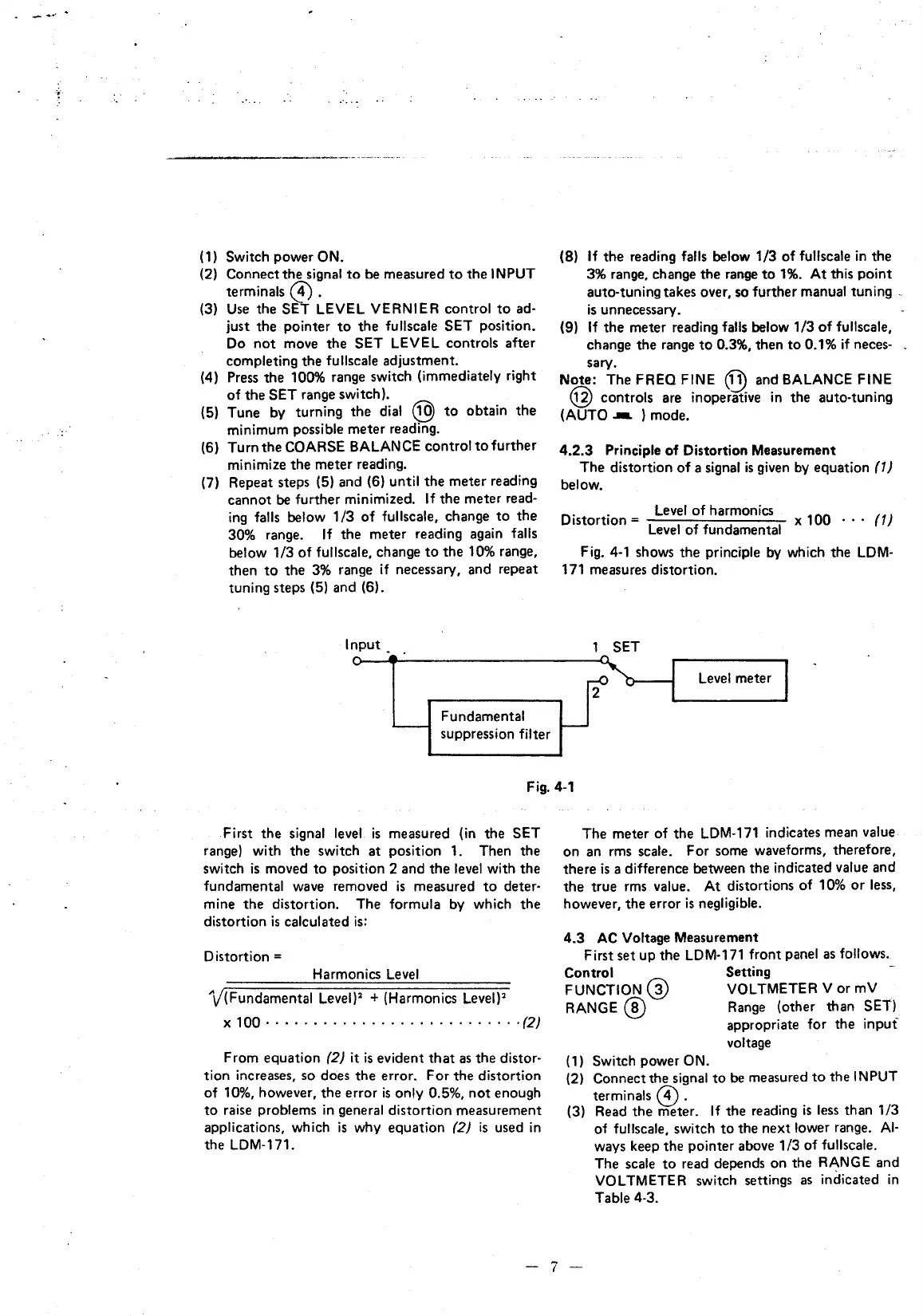
Fig.
4-1
shows the principle by which the
LDM·
171 measures distortion.
SET
Level
meter
Fig.
4-1
First
the
signal
level
is
measured (in
the
SET
range) with the switch
at
position 1. Then
the
switch
is
moved
to
position 2 and
the
level
with
the
fundamental wave removed
is
measured
to
deter-
mine
the
distortion. The formula
by
which
the
distortion
is
calculated
is:
Distortion =
Harmonics
Level
\/(Fundamental
Level)
2
+ (Harmonics
Level)>
X 100 · · · • · · · · · · · · · · · · · · · · · · · · · ·
·(2}
From equation
(2}
it
is
evident
that
as
the distor-
tion increases, so does
the
error.
For
the distortion
of
10%, however,
the
error
is
only 0.5%,
not
enough
to
raise problems
in
general distortion measurement
applications, which
is
why
equation
(2}
is
used
in
the
LDM-171.
The meter
of
the
LDM-171
indicates mean value
on
an rms scale. For some waveforms, therefore,
there
is
a difference between the indicated value and
the
true rms value. At distortions
of
10%
or
less,
however, the error
is
negligible.
4.3
AC Voltage Measurement
First set up the LDM-171 front panel
as
follows.
Control Setting
FUNCTION@
VOLTMETER V or mV
RANGE
@ Range (other than SET).
appropriate for the
inpuf
voltage
(1)
Switch power ON.
(2) Connect the signal
to
be
measured
to
the
INPUT
terminals @ .
(3) Read
the
meter.
If
the
reading
is
less than 1/3
of
fullscale, switch
to
the
next
lower range.
AI·
ways keep
the
pointer above
1/3
of fullscale.
The scale
to
read depends
on
the RANGE and
VOLTMETER switch settings
as
indicated
in
Table 4-3.
-
7-