-4··
...
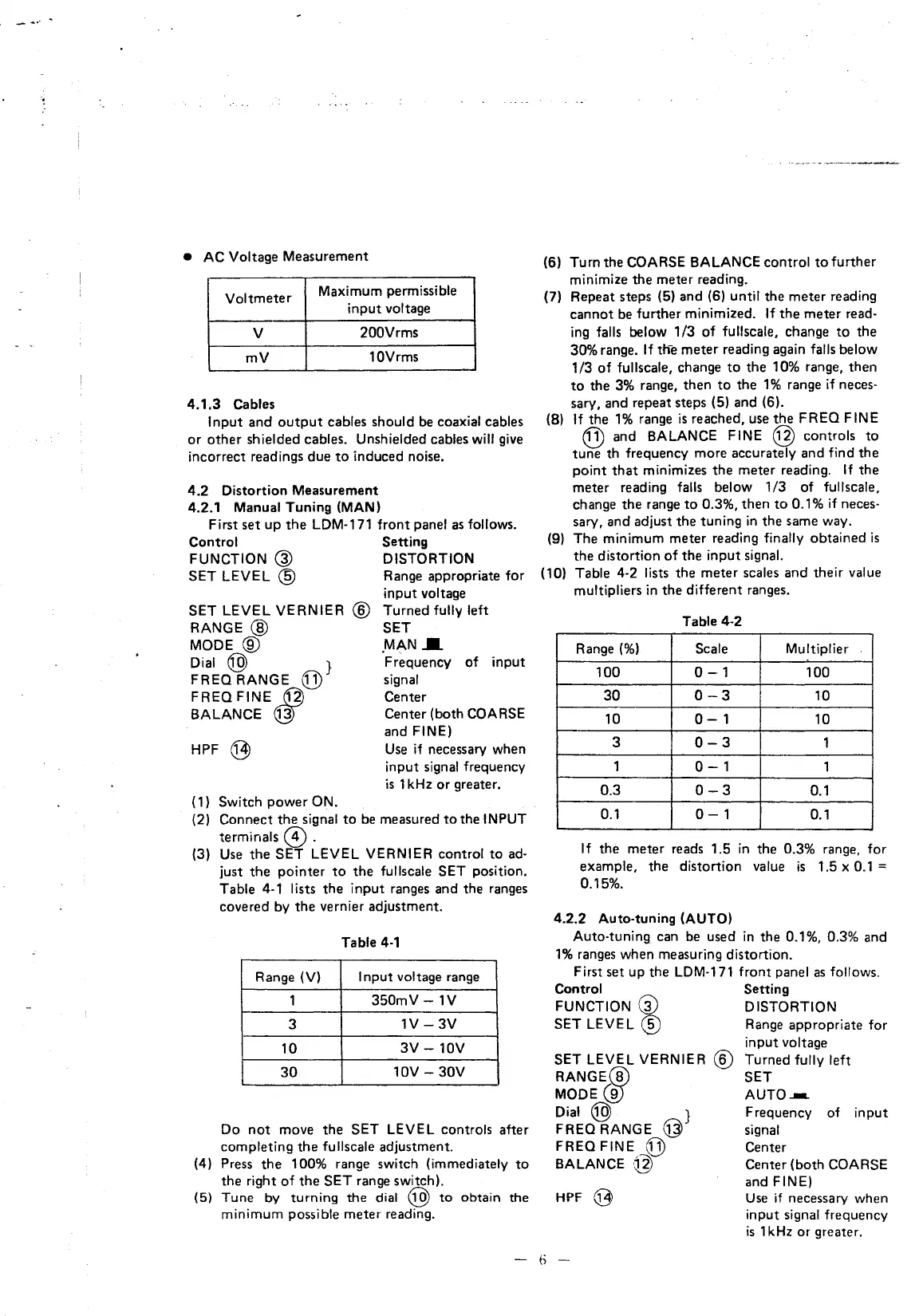
• AC Voltage Measurement
Voltmeter
Maximum permissible
input voltage
v
200Vrms
mV
10Vrms
4.1.3
Cables
Input
and
output
cables should be coaxial cables
or
other
shielded cables. Unshielded cables will
give
incorrect readings due
to
induced noise.
4.2
Distortion Measurement
4.2.1 Manual Tuning (MAN)
First
set
up
the
LDM-171
front
panel as follows.
Control Setting
FUNCTION @ DISTORTION
SET LEVEL
@ Range appropriate for
SET LEVEL VERNIER
RANGE@
MODE@
Dial@
}
FREQ RANGE
@
FREQFINE
~
BALANCE @)
HPF @
(1) Switch power ON.
input voltage
@ Turned fully left
SET
.M~NI
Frequency
of
input
signal
Center
Center {both
COARSE
and FINE)
Use
if necessary when
input signal frequency
is
1kHz
or
greater.
(2) Connect
the
signal
to
be measured
to
the INPUT
terminals @ .
(3)
Use
the
SET LEVEL VERNIER control
to
ad-
just
the
pointer
to
the
fullscale SET position.
Table 4-1 lists the input ranges and the ranges
covered by
the
vernier adjustment.
Table
4·1
Range (V)
Input
voltage range
1
350mV
-1V
3
1V-3V
10
3V
-10V
30
10V-
30V
Do
not
move
the
SET LEVEL controls after
completing
the
fullscale adjustment.
(4) Press
the
100% range switch (immediately
to
the right
of
the
SET range switch).
(5) Tune
by
turning
the
dial @
to
obtain the
minimum possible meter reading.
(6) Turn the
COARSE BALANCE control
to
further
minimize
the
meter reading.
(7) Repeat steps (5) and (6)
until the meter reading
cannot be further minimized.
If
the
meter read-
ing
falls below 1/3
of
fullscale, change
to
the
30% range. If tne meter reading again falls below
1/3
of
fullscale, change
to
the 10% range, then
to
the
3%
range, then
to
the
1%
range if neces-
sary, and repeat steps (5) and (6).
(8)
If
the
1%
range
is
reached, use
the
FREQ FINE
@ and BALANCE FINE @ controls
to
tune th frequency more accurately and find the
point
that
minimizes
the
meter reading.
If
the
meter reading
falls below 1/3
of
fullscale,
change the range
to
0.3%, then
to
0.1% if neces-
sary,
and adjust the tuning
in
the same way.
(9) The minimum meter reading finally obtained
is
the
distortion
of
the input signal.
(10) Table 4-2 lists the meter scales and their value
multipliers
in
the
different ranges.
Table 4-2
Range(%)
Scale Multiplier
100
0-1
100
30
0-3
10
10
0-1
10
3
0-3
1
1
0-1
1
0.3
0-3
0.1
0.1
0-1
0.1
If
the meter reads 1.5
in
the 0.3% range, for
example, the distortion value
is
1.5 x 0.1 =
0.15%.
4.2.2 Auto-tuning (AUTO)
Auto-tuning can
be
used
in
the 0.1%, 0.3% and
1%
ranges when measuring distortion.
First set up the
LDM-171
front panel
as
follows.
Control Setting
FUNCTION @ DISTORTION
SET LEVEL
@ Range appropriate for
input voltage
SET LEVEL VERNIER @ Turned fully left
RANGEUU SET
MODE@
AUTO--.
Dial @ } Frequency
of
input
FREO RANGE @ signal
FREQ
FINE
Q})
Center
BALANCE @ Center (both COARSE
HPF
Q3
and FINE)
Use
if necessary when
input signal frequency
is
1kHz
or
greater.
-
6-