Do you have a question about the Leadshine Technology DMA860H and is the answer not in the manual?
Details electrical parameters like output current, input voltage, logic signal current, and pulse frequency.
Covers cooling, ambient temperature, humidity, operating temperature, and vibration specifications for the drive.
Provides dimensional drawings and weight of the DMA860H stepper drive.
Offers recommendations for managing drive and motor heat to ensure reliable operation.
Details the pin functions and configurations for the control signal connector (P1).
Explains how to configure pulse edge and control signal modes using internal jumpers (J1, J2).
Describes the pin functions for the power and motor connection connector (P2).
Guides on wiring 4-lead stepper motors, including current calculation for peak output.
Explains half coil and full coil configurations for 6-lead motors, detailing their impact on speed and torque.
Describes series and parallel connection methods for 8-lead motors to optimize performance.
Discusses the use of regulated and unregulated power supplies, including selection criteria and capacity.
Provides recommendations for powering multiple drivers to reduce cost and avoid interference.
Advises on choosing appropriate supply voltage for optimal motor speed, torque, and drive reliability.
Details how to set microstep resolution using DIP switches SW5-SW8 based on desired steps per revolution.
Explains how to set the motor current using DIP switches SW1-SW3 for optimal torque and heat management.
Describes the function of SW4 for setting standstill current to half or full of the dynamic current.
Guides on using SW4 for automatic motor parameter identification and drive configuration for optimized performance.
Lists common symptoms of driver issues and their potential causes for troubleshooting.
Outlines the product warranty coverage period and terms for defects in materials and workmanship.
Specifies conditions under which the warranty is voided, such as improper handling or exceeding specifications.
Provides instructions on how to obtain warranty service, including RMA procedures and shipping.
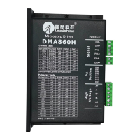
The DMA860H is a fully digital stepper drive designed for optimal performance in motion control applications. It leverages an advanced DSP control algorithm to deliver exceptional system smoothness, providing optimal torque and effectively eliminating mid-range instability. This drive is particularly well-suited for applications demanding low noise, minimal heating, high speed, and high precision.
The DMA860H's core function is to precisely control stepping motors. It achieves this through its advanced digital signal processing capabilities, which allow for fine-tuned motor operation. The drive supports both 2-phase and 4-phase hybrid stepping motors, making it versatile for a wide range of motor types. It can operate in both PUL/DIR (pulse/direction) and CW/CCW (clockwise/counter-clockwise) modes, offering flexibility in control signal interpretation. The drive incorporates optically isolated inputs for control signals, which helps to minimize electrical noise and improve system stability in interference-prone environments. For enhanced reliability, the DMA860H includes built-in protection features against over-current and over-voltage conditions, safeguarding both the drive and the motor.
The DMA860H is designed for ease of use and adaptability across various applications. A key feature is its motor auto-identification and parameter auto-configuration technology. This allows the drive to automatically detect the connected motor's parameters and configure itself for optimal performance, simplifying the setup process significantly. This feature ensures that the drive delivers the best possible responses with different motors without requiring extensive manual tuning.
The drive offers a wide range of microstep resolutions, with 16 selectable options from 400 to 40000 steps per revolution (for a 1.8° motor). This allows users to achieve very smooth motor movement and high precision, even with low-resolution step inputs, thanks to its Multi-Stepping feature. The pulse input frequency can go up to 200 KHz, accommodating high-speed applications.
For current control, the DMA860H provides 8 selectable peak current settings, ranging from 2.40A to 7.20A. This allows users to match the drive's output current to the motor's requirements, optimizing torque and preventing overheating. The drive also supports an automatic idle-current reduction function, which can significantly reduce motor and driver heating when the motor is stopped. This feature can reduce motor heating to 36% of its original value, contributing to longer motor life and improved system reliability.
The DMA860H features a soft-start function, which eliminates any "jump" when the drive is powered on, ensuring a smooth and controlled startup. The drive can be powered by either 18-80VAC or 26-113VDC, offering flexibility in power supply choices. It is suitable for a broad spectrum of stepping motors, from NEMA size 23 to 42, making it a versatile component for various machine designs. Typical applications include X-Y tables, engraving machines, labeling machines, laser cutters, and pick-place devices, especially where low noise, low heating, high speed, and high precision are critical.
The control signal interface (P1) can accept differential and single-ended inputs, including open-collector and PNP outputs. This broad compatibility ensures that the drive can be easily integrated with various controllers. Jumpers J1 and J2 inside the drive allow users to select the active pulse edge (rising or falling) and the control signal mode (PUL/DIR or CW/CCW), providing further customization options.
The DMA860H is designed with features that contribute to its longevity and ease of maintenance. The automatic idle-current reduction function not only improves performance but also reduces heating, which is a major factor in component wear and tear. By reducing heat, the drive and motor can operate reliably for longer periods.
Proper heat dissipation is crucial for the drive's reliable operation. The manual recommends mounting the driver vertically to maximize the heat sink area and suggests using forced cooling methods if necessary to keep the driver's working temperature below 70°C (158°F) and the motor's temperature below 80°C (176°F).
The built-in over-current and over-voltage protections are critical maintenance features. In the event of these conditions, the drive will activate the protection, causing the motor shaft to become free or the red LED to blink. To reset the driver and restore proper function, users simply need to repower it after resolving the underlying problem. This prevents permanent damage to the drive and motor, reducing the need for costly repairs or replacements.
For troubleshooting, the manual provides guidance on identifying common problems, such as the motor not rotating, rotating in the wrong direction, erratic motion, or stalling during acceleration, as well as excessive heating. It suggests checking for issues like incorrect microstep resolution or current settings, faulty motor coils, or inadequate power supply. This structured approach to troubleshooting helps users quickly diagnose and resolve issues, minimizing downtime.
Wiring notes emphasize the importance of using twisted pair shield cables to improve anti-interference performance and separating pulse/direction signal wires from motor wires to prevent noise coupling. These recommendations contribute to system stability and reduce the likelihood of operational errors, which can often be mistaken for hardware faults. The prohibition against pulling and plugging connector P2 while the drive is powered on is a critical safety and maintenance instruction, as it prevents extremely high back-EMF voltage surges that could damage the drive.
The auto-tuning feature, activated by toggling SW4, allows the drive to identify motor parameters and calculate current loop parameters for optimized performance. This is particularly useful during initial installation or if the motor or power supply is changed, ensuring the drive always operates at its best without complex manual adjustments.
| Control Signal | TTL compatible |
|---|---|
| Input Voltage | 20-80 VDC |
| Protection Features | Over-voltage, over-current |
| Logic Signal Current | 6-16 mA |
| Pulse Input Frequency | 0 to 200 kHz |
| Operating Temperature | 0°C to +50°C |
| Storage Temperature | -20 to +70 °C |
| Humidity | 5% to 95% (non-condensing) |