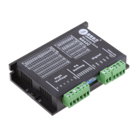
M542C Full Digital Stepper Drive Manual V2.0
6
a power supply of lower current rating than that of motor (typically 50%~70% of motor current). The reason is that
the drive draws current from the power supply capacitor of the unregulated supply only during the ON duration of the
PWM cycle, but not during the OFF duration. Therefore, the average current withdrawn from power supply is
considerably less than motor current. For example, two 3A motors can be well supplied by one power supply of 4A
rating.
4.5.2 Multiple Drives
It is recommended to have multiple drives to share one power supply to reduce cost, if the supply has enough capacity.
To avoid cross interference, DO NOT daisy-chain the power supply input pins of the drives. (Instead, please connect
them to power supply separately.)
4.5.3 Selecting Supply Voltage
The power MOSFETS inside the M542C can actually operate within +20~+50VDC, including power input fluctuation
and back EMF voltage generated by motor coils during motor shaft deceleration. Higher supply voltage can increase
motor torque at higher speeds, thus helpful for avoiding losing steps. However, higher voltage may cause bigger motor
vibration at lower speed, and it may also cause over-voltage protection or even drive damage. Therefore, it is suggested
to choose only sufficiently high supply voltage for intended applications, and it is suggested to use power supplies with
theoretical output voltage of +20 ~ +45VDC, leaving room for power fluctuation and back-EMF.
4.6 Wiring Notes
In order to improve anti-interference performance of the drive, it is recommended to use twisted pair shield cable.
To prevent noise incurred in PUL/DIR signal, pulse/direction signal wires and motor wires should not be tied up
together. It is better to separate them by at least 10 cm, otherwise the disturbing signals generated by motor will
easily disturb pulse direction signals, causing motor position error, system instability and other failures.
If a power supply serves several drives, separately connecting the drives is recommended instead of
daisy-chaining.
It is prohibited to pull and plug connector P2 while the drive is powered ON, because there is high current flowing
through motor coils (even when motor is at standstill). Pulling or plugging connector P2 with power on will cause
extremely high back-EMF voltage surge, which may damage the drive.
5 Selecting Microstep Resolution and drive Output Current
This drive uses an 8-bit DIP switch to set microstep resolution, and motor operating current, as shown below:
5.1 Microstep Resolution Selection
Microstep resolution is set by SW5, 6, 7, 8 of the DIP switches as shown in the following table:

 Loading...