Do you have a question about the Leadshine Technology CS-D1008E and is the answer not in the manual?
Lists key features of the CS-D1008E closed loop stepper drive, including performance and capabilities.
Outlines various industrial applications where the CS-D1008E closed loop stepper drive is suitable.
Provides detailed electrical parameters including voltage, current, and frequency ratings for the drive.
Specifies the operating and storage environmental conditions, including temperature, humidity, and vibration.
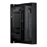
Details the physical dimensions and mechanical aspects of the drive, including mounting.
Offers guidance on managing heat generated by the drive during operation to ensure optimal performance.
Details for P1 connector, including pin assignments and control signal connections.
Details for P2 connector, covering outputs like brake, in-position, and alarm signals.
Pin assignments and details for the encoder input connection.
Specifies pin connections for motor phases and power supply input.
Describes the RS232 communication port for PC connection and parameter modification.
Explains the function and meaning of the drive's status indicator LEDs.
Discusses the use of regulated versus unregulated power supplies for optimal drive performance.
Provides recommendations for sharing a single power supply across multiple drives to save space and cost.
Offers advice on selecting the appropriate supply voltage, considering fluctuations and back EMF.
Explains how to use the S1 rotating switch to set peak current and motion gains.
Details the 8-bit DIP switch S2 for configuring microstep resolution and current settings.
Describes the microstep settings configured by DIP switches SW1, SW2, SW3, and SW4.
Explains how DIP switches SW5 through SW8 are used to set rotation direction, control mode, and pulse mode.
Details the S3 selector switch for configuring control signal voltage levels.
Outlines the standard 12-month warranty period for defects in materials and workmanship.
Lists conditions and damages that are not covered by the product warranty.
Instructions on how to obtain warranty service, including contacting the seller for an RMA.
Guidance on returning failed products for warranty or repair services, including contact information.
| Control Mode | Pulse/Direction or CW/CCW |
|---|---|
| Protection Features | Over-voltage, Over-current |
| Operating Temperature | 0°C to +50°C |
| Storage Temperature | -20°C to +70°C |
| Humidity | 40-90%RH (Non-condensing) |