CS-D1008E Closed Loop Stepper Drive User Manual
Page | 4
3. Connections and LED Indication
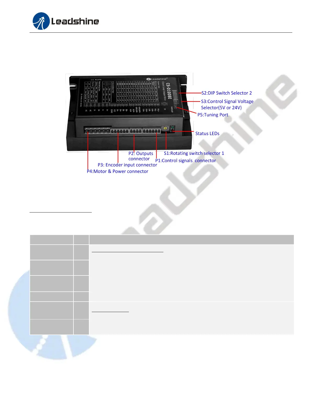
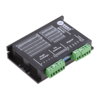
A CS-D1008E closed loop stepper drive has 5 connection blocks from P1 to P5 (see figure 2).
Figure 2: CS-D1008E connectors
3.1 Connector P1 – Control Signals Connector
3.1.1 Pin Assignments of P1
The P1 connector in Figure 2 contains connections for control signals.
See the following table for details.
Pulse and Direction Connection:
(1) Optically isolated, high level 4.5-5V or 24V, low voltage 0-0.5V
(2) Max 500 KHz input frequency for 5V control signal, while max 200KHz for 24V.
(3) The width of PUL signal is at least 1.0μs or 2.5μs, duty cycle is recommended 50%
(4) Single pulse (step & direction) or double pulse (CW/CCW) is set by DIP Switch SW7
(5) DIR signal requires advance PUL signal minimum 5 μs in single pulse mode
(6) The factory setting of control signal voltage is 24V, must need to set S3 (figure 2) if it
is 5V
Enable Signals: Optional, no connected default.
(1) Effective high level is 4.5-24V; Effective low level is 0-0.5V connection
(2) ENA signal requires advance DIR signal minimum 200ms in single pulse mode,
Notes: (1) Shielding control signal wires is suggested; (2) To avoid/reduce interference, do not tie control signal cables
and power wires together; (3) Brake output need to connect a relay and diode