CS-D1008E Closed Loop Stepper Drive User Manual
Page | 10
3) Usually keep factory settings
output
current
fluctuates
from 3-6A
following
the load)
Note: “factory” means the factory switch setting, “default” means the parameters can be set by Leadshine software.
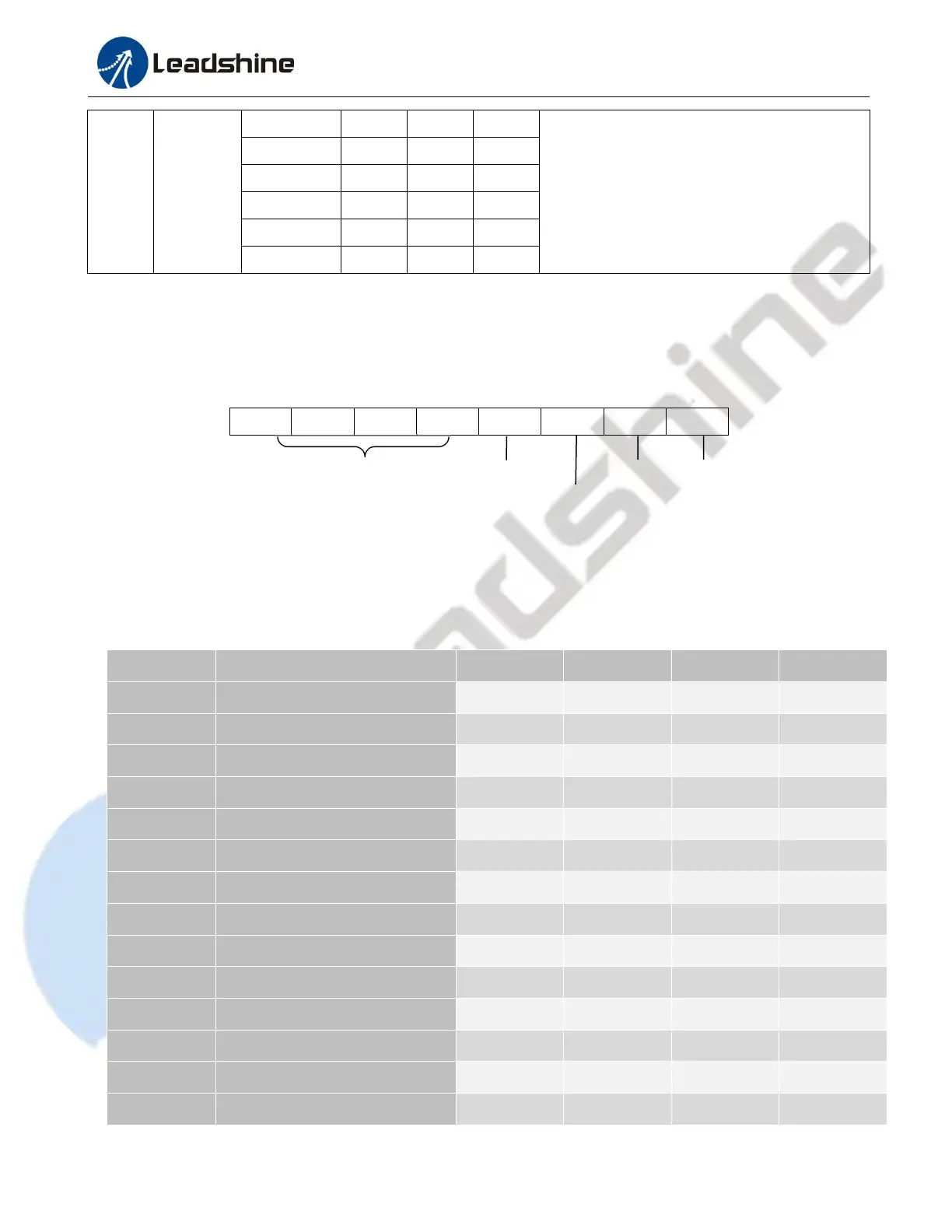
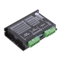
6.2 S2 - DIP Switch Configurations
The 8-bit is located on the side (DIP switch S2 in Figure 2) and used to configure settings of micro step resolution,
output current, and motor standstill current as shown below.
Figure 6: DIP switches
6.2.1 Micro Step (SW1-SW4)
Each CS-D1008E has 15 microstep settings which can be configured through DIP switches SW1, SW2, SW3 and SW4.
See the following table for detail.
Pulses/Rev. (for 1.8°motor)