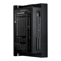
CS-D1008E Closed Loop Stepper Drive User Manual
Page | 5
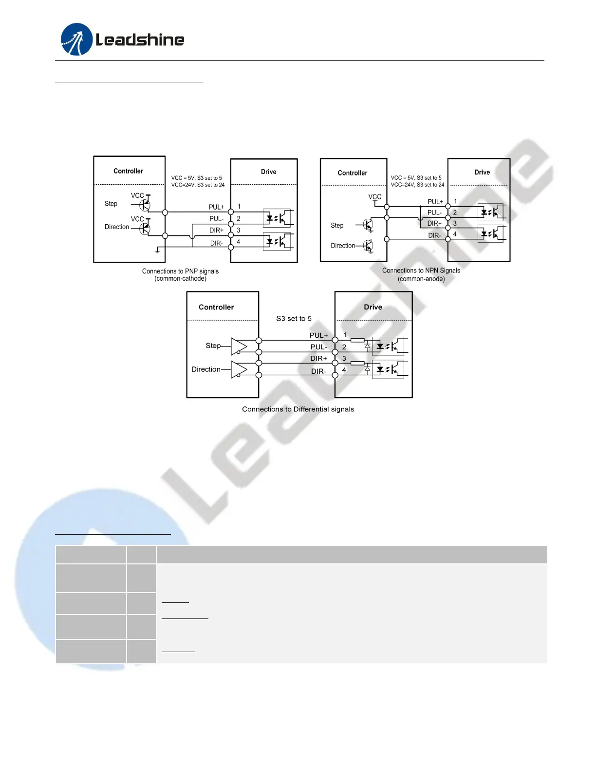
3.1.2 Connection of Control Signals
The CS-D1008E can accept differential and single-ended control signal inputs (open-collector and PNP output). A
CS-D1008E has 3 optically isolated control inputs, PUL, DIR, and ENA. Refer to the following two figures for
connections of open-collector and PNP signals.
Figure 3: Control Signals Connection
Notes: (1) ENA signal is no connected as default;
(2) Control signal amplitude is 24 V as default. If it is 12 V, please set the S3 (Figure 2) selector switch to 5 V first,
then connect 1KΩ resistor; If it is 5V, please set the S3 to 5V.
3.2 Connector P2 – Outputs Connector
3.2.1 Pin Assignments of P2
Select Brake or In position function via DIP Switch SW8
Brake: Max. 30VDC@100mA, connect with brake coil, relay and diode.
In position: A configurable OC output signal. It takes a sinking or sourcing,
30VDC@100mA
Alarm: A configurable OC output signal. It takes a sinking or sourcing, 30VDC@100mA