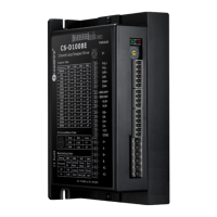
CS-D1008E Closed Loop Stepper Drive User Manual
Table of Content
1. Introduction.....................................................................................................................................................................1
1.1 Features...................................................................................................................................................................1
1.2 Applications............................................................................................................................................................ 1
2. Specifications...................................................................................................................................................................2
2.1 Electrical Specifications......................................................................................................................................... 2
2.2 Environment............................................................................................................................................................2
2.3 Mechanical Specifications......................................................................................................................................3
2.4 Heat Dissipation......................................................................................................................................................3
3. Connections and LED Indication..................................................................................................................................4
3.1 Connector P1 – Control Signals Connector........................................................................................................... 4
3.1.1 Pin Assignments of P1.................................................................................................................................4
3.1.2 Connection of Control Signals.................................................................................................................... 5
3.2 Connector P2 – Outputs Connector........................................................................................................................5
3.2.1 Pin Assignments of P2.................................................................................................................................5
3.2.2 Connection of In-position and Alarm..........................................................................................................6
3.2.3 Connection of Brake Signal.........................................................................................................................6
3.3 Connector P3 - Encoder Connector........................................................................................................................7
3.4 Connector P4 - Motor & Power Connection..........................................................................................................7
3.5 Connector P5 – Tuning Port................................................................................................................................... 8
3.6 LED Light Indication..............................................................................................................................................8
4. Motor Selection............................................................................................................................................................... 8
5. Power Supply Selection.................................................................................................................................................. 8
5.1 Regulated or Unregulated Power Supply............................................................................................................... 9
5.2 Power Supply Sharing............................................................................................................................................ 9
5.3 Selecting Supply Voltage........................................................................................................................................9
6. DIP Switch Configurations............................................................................................................................................ 9