CS-D1008E Closed Loop Stepper Drive User Manual
Page | 7
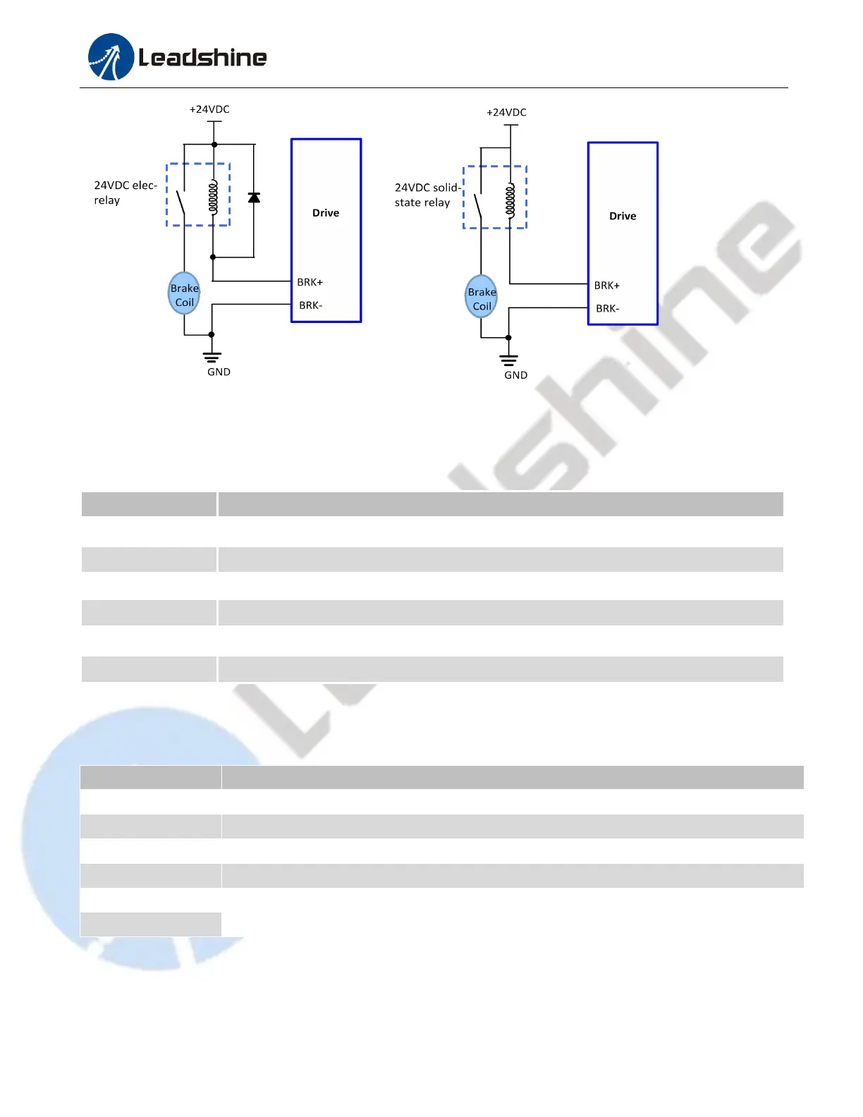
Figure 5: Brake Output Connection
3.3 Connector P3 - Encoder Connector
The P3 connector in Figure 2 is for encoder signal connection. Refer to the following table for details.
Encoder B+ input connection
Encoder B- input connection
Encoder A+ input connection
Encoder A- input connection
Encoder +5V voltage output connection
3.4 Connector P4 - Motor & Power Connection
The P4 connector in Figure 2 is for motor and power connection. Refer to the following table for details.
Stepper motor A+ connection. Connect motor A+ wire to this pin
Stepper motor A- connection. Connect motor A- wire to this pin
Stepper motor B+ connection. Connect motor B+ wire to this pin
Stepper motor B- connection. Connect motor B- wire to this pin
Power supply input 18-80VAC or 24-110 VDC(recommended 20-70VAC or 30-90VDC);
No polarity
Notes: If using an AC transformer, be sure to use a transformer with isolation.Otherwise there is a risk of electrocution