Do you have a question about the Leadshine Technology M542C and is the answer not in the manual?
Lists key features of the M542C drive, including anti-resonance and multi-stepping capabilities.
Suitable for various machines like X-Y tables, engraving, labeling, laser cutters, and pick-place devices.
Details electrical parameters such as input voltage, output peak current, logic signal current, and frequency.
Covers ambient temperature, humidity, storage temperature, operating temperature, and vibration limits.
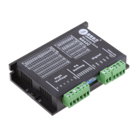
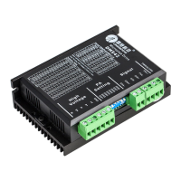
Provides physical dimensions and mounting details, including diagrams and measurements.
Recommendations for managing drive and motor heat through idle current reduction and mounting.
Describes the pinout and function of the P1 control signal connector for PUL, DIR, and ENA signals.
Describes the pinout and function of the P2 connector for power supply and motor phase connections.
Explains how to connect differential and single-ended control signals to the P1 connector.
Details the wiring procedure for 4-lead stepper motors, including phase connections.
Covers wiring for 6-lead motors in half coil and full coil configurations for different performance needs.
Explains wiring for 8-lead motors in series and parallel configurations for flexibility.
Guides on selecting appropriate supply voltage and current for the drive to achieve good performance.
Discusses the advantages and considerations of using regulated versus unregulated power supplies.
Provides recommendations for powering multiple drives to reduce cost and avoid interference issues.
Advises on choosing the correct supply voltage range for optimal performance and safety.
Important notes and precautions for wiring, including cable types and connector handling during operation.
Explains how to set microstep resolution using DIP switches SW5, 6, 7, and 8.
Discusses factors affecting output current selection and its impact on motor performance and heating.
Details how to set the dynamic current level using DIP switches SW1, 2, and 3 based on motor requirements.
Explains how to set standstill current using DIP switch SW4 to reduce holding torque when idle.
Describes the drive's feature for automatic motor parameter setup upon power-on for optimal torque.
Lists common motor and drive problems with their potential causes for effective troubleshooting.
Outlines the warranty period and terms for product defects against materials and workmanship.
Lists conditions and customer actions such as improper handling or misuse that void the product warranty.
Provides instructions on how to obtain warranty service, including obtaining an RMA number.
States limitations on implied warranties like merchantability and fitness for a particular purpose.
Instructions for returning products under warranty, including necessary documentation and contact details.
The M542C is a full digital stepper drive designed for use with 2-phase and 4-phase stepper motors, ranging in size from NEMA 17 to NEMA 24. It is an ideal choice for high-requirement applications due to its advanced DSP control algorithm, which provides exceptional system smoothness, optimal torque, and effectively nullifies mid-range instability. This drive significantly reduces motor noise and heating, and ensures smoother movement compared to traditional analog drives.
The core function of the M542C is to precisely control the movement of stepper motors. It achieves this through a fully digital design, leveraging advanced DSP control algorithms. This digital approach allows for superior performance characteristics, particularly in terms of motion smoothness and torque delivery.
A key feature is its motor auto-identification and parameter auto-configuration. Upon power-on, the drive automatically identifies the connected motor and configures its parameters to achieve optimal performance. This eliminates the need for manual tuning, simplifying setup and ensuring the motor operates efficiently with the drive. The drive calculates optimal parameters for current control after this process, allowing the stepper motor to output optimal torque.
The M542C supports a wide range of microstep resolutions, offering 15 selectable options from 400 to 25000 steps per revolution for a 1.8° motor. This "Multi-Stepping" capability allows a low-resolution step input from a controller to produce a much higher microstep output, resulting in significantly smoother motor movement and reduced vibration, especially at lower speeds.
It operates in PUL/DIR mode, accepting pulse and direction signals for motor control. The pulse signal (PUL+, PUL-) dictates the step movement, with each rising edge being active. The direction signal (DIR+, DIR-) determines the motor's rotation direction. The drive also includes an enable signal (ENA+, ENA-) which, when activated, deactivates the drive, freeing the motor. By default, this is usually left unconnected, meaning the drive is enabled.
The drive incorporates automatic idle-current reduction, a feature that reduces the current supplied to the motor when it is at a standstill. This helps to minimize motor and drive heating, contributing to improved efficiency and longevity.
The M542C is designed for ease of use and adaptability across various applications. Its auto-identification and auto-configuration features simplify the initial setup process, making it accessible even for users without extensive experience in stepper motor tuning.
The drive offers 8 selectable peak current settings, allowing users to match the drive's output to the specific current requirements of their motor. This flexibility ensures that the motor receives the appropriate current for optimal torque without overheating. The current settings are configured via DIP switches, with separate settings for dynamic current and standstill current. The standstill current can be set to either half or the same as the selected dynamic current, providing further control over motor heating and power consumption when the motor is idle.
The input voltage range of 20-50VDC makes it compatible with a variety of power supplies. When selecting a power supply, it's important to consider that higher supply voltage generally improves high-speed performance, while lower voltage can reduce noise and heating at lower speeds. Both regulated and unregulated power supplies can be used, with unregulated supplies often preferred due to their ability to handle current surges.
For control signal connections, the M542C features optically isolated logic inputs. This isolation helps to minimize or eliminate electrical noise interference from the control signals, enhancing the drive's reliability in noisy environments. It can accept differential and single-ended inputs, including open-collector and PNP outputs, providing flexibility in connecting to various controllers.
Wiring considerations are crucial for optimal performance. It is recommended to use twisted pair shielded cables for control signals to improve anti-interference. Pulse/direction signal wires and motor wires should be kept separate by at least 10 cm to prevent interference that could lead to motor position errors or system instability. When multiple drives share a single power supply, separate connections for each drive are recommended instead of daisy-chaining to avoid cross-interference.
The drive's mechanical specifications indicate a compact design, making it suitable for integration into various machines. For optimal heat dissipation, side mounting is recommended, and forced cooling methods can be employed if necessary, especially in demanding applications or environments.
The M542C is built with several protection functions to enhance reliability and prevent damage to the drive and motor. These include:
When any of these protections are active, the motor shaft will become free, and a red LED on the drive will blink, indicating a fault condition. To reset the drive and restore normal operation, the power must be cycled after resolving the underlying problem (e.g., reducing the current, correcting the voltage).
The automatic idle-current reduction feature also contributes to maintenance by reducing motor and drive heating during standstill, thereby extending the lifespan of both components.
In case of operational issues, the manual provides a comprehensive troubleshooting guide, listing common symptoms and their possible causes. This guide helps users identify whether a problem is electrical or mechanical and assists in isolating the faulty component. Documenting each troubleshooting step is advised, as this information can be valuable for technical support if further assistance is needed.
The drive is covered by a twelve-month limited warranty against defects in materials and workmanship. This warranty ensures that Leadshine will repair or replace defective products at its option. However, the warranty does not cover damage due to improper handling, wiring, unauthorized modification, misuse, or operation outside specified electrical or environmental parameters. For warranty service, customers must obtain a Returned Material Authorization (RMA) number from Leadshine's customer service.
| Input Voltage | 20-50 VDC |
|---|---|
| Pulse Input Frequency | 0-200 kHz |
| Interface | Pulse and Direction |
| Isolation Resistance | 500MΩ |
| Protection Features | Over-voltage, Over-current, Over-temperature |
| Operating Temperature | 0°C to +50°C |
| Storage Temperature | -20°C to +70°C |
| Humidity | 5% to 95% (non-condensing) |