Do you have a question about the Leadshine Technology MA860C and is the answer not in the manual?
Details the key features of the MA860C digital stepper drive, including anti-resonance and auto-identification.
Lists suitable applications for the MA860C drive, focusing on machines requiring low noise, low heating, high speed, and high precision.
Presents the electrical parameters of the MA860C drive, including output peak current, input voltage, and pulse frequency.
Details the environmental conditions and other specifications for the MA860C drive, such as cooling and storage temperature.
Provides the mechanical dimensions and weight of the MA860C stepper drive.
Offers recommendations for managing drive and motor heating, including idle-current mode and mounting orientation.
Describes the pin functions and configurations for the P1 connector used for control signals.
Explains how to select microstep resolution and control signal mode using internal jumpers CN6 and CN7.
Details the pin functions for the P2 connector, which handles power and motor connections.
Illustrates the interface for control signal connections to the P1 connector, including open-collector and PNP inputs.
Provides guidance on wiring 4-lead stepping motors to the MA860C drive.
Explains wiring configurations for 6-lead stepping motors, covering half coil and full coil options.
Details the half coil connection method for 6-lead motors, suitable for higher speeds.
Details the full coil connection method for 6-lead motors, suitable for higher torque at lower speeds.
Describes wiring options for 8-lead stepping motors, including series and parallel configurations.
Details the series connection method for 8-lead motors, used for higher torque at lower speeds.
Details the parallel connection method for 8-lead motors, offering stability and higher torque at higher speeds.
Guides users on selecting appropriate AC or DC power supplies for the MA860C drive.
Provides essential notes for wiring to improve anti-interference performance and prevent noise.
Explains how to set the microstep resolution using the DIP switches SW5, 6, 7, and 8.
Discusses how to set the drive output current for optimal torque and to prevent overheating.
Details how to set the dynamic peak and RMS current using DIP switches SW1, 2, and 3.
Explains the setting for standstill current using DIP switch SW4, which reduces current when the motor is stopped.
Describes the drive's automatic function to identify motor parameters for optimal torque.
Lists common symptoms encountered with the stepper drive and their potential causes for troubleshooting.
Outlines the warranty terms and conditions for Leadshine products.
Specifies conditions and damages that are not covered by the product warranty.
Provides instructions on how to obtain warranty service, including RMA procedures.
States the limitations of Leadshine's warranty, including disclaimers for implied warranties.
Instructions for shipping products that fail during the warranty period for service.
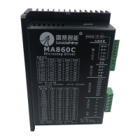
The Leadshine MA860C is a fully digital stepper drive designed for precise motion control applications. It leverages advanced DSP control algorithms to deliver exceptional performance, characterized by smooth motor movement, optimal torque output, and effective suppression of mid-range instability. This drive is particularly well-suited for applications demanding low noise, minimal heating, high speed, and high precision.
The MA860C functions as a control unit for 2-phase and 4-phase stepping motors, converting digital control signals into precise motor movements. It supports both PUL/DIR (pulse/direction) and CW/CCW (clockwise/counter-clockwise) control modes, offering flexibility in integration with various control systems. The drive's core functionality revolves around its ability to interpret incoming pulse and direction signals to accurately position and move a connected stepper motor.
A key feature of the MA860C is its motor auto-identification and parameter auto-configuration. Upon power-up, the drive automatically identifies the connected motor and configures its internal parameters for optimal performance. This eliminates the need for manual tuning and ensures that the drive operates efficiently with different motors, providing tailored responses.
The drive incorporates Multi-Stepping technology, which allows a low-resolution step input from the controller to be translated into a higher microstep output. This results in significantly smoother motor movement, reducing vibrations and improving the overall quality of motion, especially at lower speeds.
For enhanced reliability and protection, the MA860C includes built-in over-voltage and over-current protection features. These safeguards prevent damage to the drive and the motor in the event of abnormal operating conditions, such as excessive current draw or high input voltage. When a protection function is activated, the motor shaft will become free, and a red LED on the drive will blink, indicating the specific fault. The drive can be reset by cycling its power after the problem has been resolved.
The MA860C is designed for ease of use and integration into various stepping motor systems. It accepts optically isolated control signals, which helps to minimize electrical noise interference and ensures robust communication with the controller. The input signals are TTL compatible, making it compatible with a wide range of industrial control systems.
Users can select from 16 different microstep resolutions, ranging from 400 to 40000 steps per revolution for a 1.8° motor. This allows for fine-tuning of the motor's resolution to meet the specific precision requirements of an application. The microstep resolution is easily set using a DIP switch on the drive.
The drive also offers 8 selectable peak output current settings, allowing users to match the drive's current output to the motor's rated current. This is crucial for achieving optimal torque and preventing motor overheating. The dynamic current setting is also configured via DIP switches.
A "soft-start" feature ensures that the motor begins movement smoothly without any sudden "jump" when powered on, contributing to system longevity and reduced mechanical stress.
The MA860C supports automatic idle-current reduction. This feature automatically reduces the motor current to 50% of the selected dynamic current one second after the last pulse. This significantly reduces motor and drive heating when the motor is at a standstill, improving efficiency and extending the lifespan of both components.
The drive is suitable for a broad range of stepping motors, typically those with frame sizes from NEMA24 to NEMA34. It finds applications in diverse machinery such as X-Y tables, engraving machines, labeling machines, laser cutters, and pick-and-place devices. Its ability to deliver low noise, low heating, high speed, and high precision makes it an ideal choice for demanding industrial environments.
For wiring, the manual provides detailed instructions for connecting 4-lead, 6-lead, and 8-lead motors, including configurations for higher speed or higher torque operations. It also offers guidance on selecting appropriate power supplies, emphasizing the benefits of AC power for higher torque and the considerations for using regulated or unregulated DC supplies. The drive can operate with input voltages between 18-80VAC or 30-100VDC.
The MA860C is designed for reliable operation with minimal maintenance. The automatic idle-current reduction feature inherently contributes to reduced heating, which is a major factor in component wear and tear. By keeping the motor and drive cooler during idle periods, the lifespan of the system is extended.
Proper installation is crucial for long-term reliability. The manual recommends mounting the drive vertically to maximize heat dissipation from its heat sink area. In environments where high ambient temperatures or heavy loads are present, forced cooling methods (e.g., fans) are suggested to maintain the drive's reliable working temperature below 45°C (113°F) and the motor's temperature below 80°C (176°F).
The use of twisted pair shielded cables for control signals is recommended to improve anti-interference performance, which helps prevent erratic motor motion caused by electrical noise. Additionally, keeping pulse/direction signal wires and motor wires separated by at least 10 cm is advised to avoid interference and ensure system stability.
The protection functions, indicated by the blinking red LED, serve as diagnostic tools, alerting users to over-current or over-voltage conditions. This allows for prompt identification and resolution of potential issues before they lead to permanent damage.
The manual includes a "Frequently Asked Questions" section with a troubleshooting guide that lists common symptoms and their possible causes, such as the motor not rotating, rotating in the wrong direction, erratic motion, or excessive heating. This guide assists users in diagnosing and resolving minor operational issues, reducing the need for external technical support.
Leadshine offers a twelve-month limited warranty against defects in materials and workmanship, providing assurance of product quality. For warranty service, customers are guided to obtain a Returned Material Authorization (RMA) number and provide a written description of the problem, facilitating efficient repair or replacement.
| Input Voltage | 20-80 VDC |
|---|---|
| Peak Current | 7.0 A |
| Protection Features | Over-voltage, Over-current, Over-temperature |
| Logic Input Current | 10 mA |
| Pulse Input Frequency | 0-200 kHz |
| Isolation Resistance | 500MΩ |
| Operating Temperature | 0°C to +50°C |
| Storage Temperature | -20°C to +70°C |
| Control Method | Pulse/Direction or CW/CCW |
| Humidity | 0-90% RH (non-condensing) |