MA860C Full Digital Stepper Drive Manual V1.0
4 Wiring
4.1 Control Signal Connector (P1) Interface
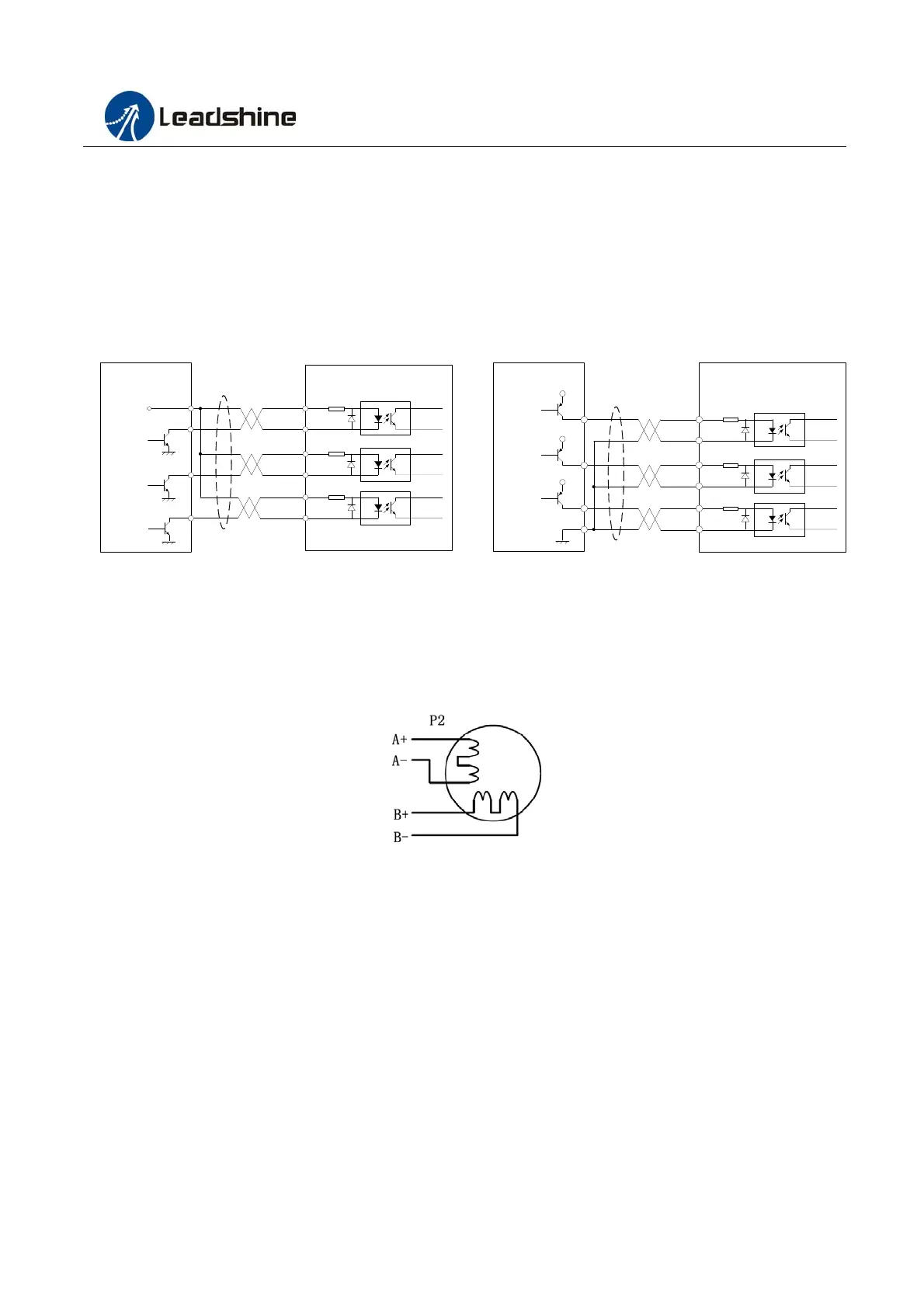
The MA860C can accept differential and single-ended inputs (including open-collector and PNP output). The MA860C
has 3 optically isolated logic inputs which are located on connector P1 to accept line drive control signals. These inputs
are isolated to minimize or eliminate electrical noises coupled onto the drive control signals. Recommend use line
drive control signals to increase noise immunity of the drive in interference environments. In the following figures,
connections to open-collector and PNP signals are illustrated(Wiring according to the correct order of P1 interface).
Figure 3: Connections to open-collector Figure 4: Connection to PNP signal (common-cathode)
signal (common-anode)
4.2 Connections of 4-lead Motor
4 lead motors are the least flexible but easiest to wire. Speed and torque will depend on winding inductance. In setting
the drive output current, multiply the specified phase current by 1.4 to determine the peak output current.
Figure 5: 4-lead Motor Connections
4.3 Connections of 6-lead Motor
Like 8 lead stepping motors, 6 lead motors have two configurations available for high speed or high torque operation.
The higher speed configuration, or half coil, is so described because it uses one half of the motor’s inductor windings.
The higher torque configuration, or full coil, uses the full windings of the phases.
4.3.1 Half Coil Configurations
As previously stated, the half coil configuration uses 50% of the motor phase windings. This gives lower inductance,
hence, lower torque output. Like the parallel connection of 8 lead motor, the torque output will be more stable at higher
speeds. This configuration is also referred to as half chopper. In setting the drive output current multiply the specified
per phase (or unipolar) current rating by 1.4 to determine the peak output current.
Drive
Controller
VCC
PUL-
PUL+
ENA-
PUL
DIR
ENABLE
DIR-
DIR+
ENA+
Drive
Controller
VCC
PUL-
PUL+
ENA-
PUL
DIR
ENABLE
DIR-
DIR+
ENA+