Do you have a question about the Leadshine DM Series and is the answer not in the manual?
The Leadshine DM stepper drive is a fully digital stepper drive that utilizes an advanced DSP control algorithm, based on the latest motion control technology. It offers a unique level of system smoothness, providing optimal torque and nulling mid-range instability. Its motor auto-identification and parameter auto-configuration feature allow for quick setup to optimal modes with various motors. Compared to traditional analog drives, the DM stepper drive operates with significantly lower noise, reduced heating, and smoother movement. These unique features make the DM drive an ideal choice for high-requirement applications.
The DM series stepper drives are categorized into two main groups:
| Part Number | Input Voltage (VDC) | Typical Supply Voltage (VDC) | Output Current (Amp) | Pulse Frequency (KHz) |
|---|---|---|---|---|
| DM320C | 18-30 | 24 | 0.5-2.0 | 70 |
| DM422C | 18-40 | 24 | 0.3-2.2 | 75 |
| DM422 | 18-40 | 24 | 0.3-2.2 | 75 |
| DM432C | 18-40 | 24 | 0.3-3.2 | 200 |
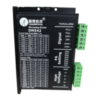
| DM442 | 18-40 | 24 | 0.5-4.2 | 200 |
| DM556 | 18-50 | 36 | 0.5-5.6 | 200 |
| DM856 | 18-80 | 68 | 0.5-5.6 | 200 |
| DM870 | 18-80 | 68 | 0.5-7.0 | 200 |
| Part Number | Input Voltage (VAC) | Typical Supply Voltage (VAC) | Output Current (Amp) | Pulse Frequency (KHz) |
|---|---|---|---|---|
| DM1182 | 80-150 | 110 | 0.5-8.2 | 200 |
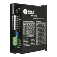
| DM2282 | 80-220 | 220 | 0.5-8.2 | 200 |
| Brand | Leadshine |
|---|---|
| Model | DM Series |
| Category | Control Unit |
| Language | English |