Digital Stepper Drive Hardware Installation Manual
9. Wiring Notes
In order to improve anti-interference performance of the drive, it is recommended to use twisted pair shield cable.
To prevent noise incurred in PUL/DIR signal, pulse/direction signal wires and motor wires should not be tied up together. It is
better to separate them by at least 10 cm, otherwise the disturbing signals generated by motor will easily disturb pulse direction
signals, causing motor position error, system instability and other failures.
If a power supply serves several drives, separately connecting the drives is recommended instead of daisy-chaining.
It is prohibited to pull and plug connector P2 while the drive is powered ON, because there is high current flowing through motor
coils (even when motor is at standstill). Pulling or plugging connector P2 with power on will cause extremely high back-EMF
voltage surge, which may damage the drive.
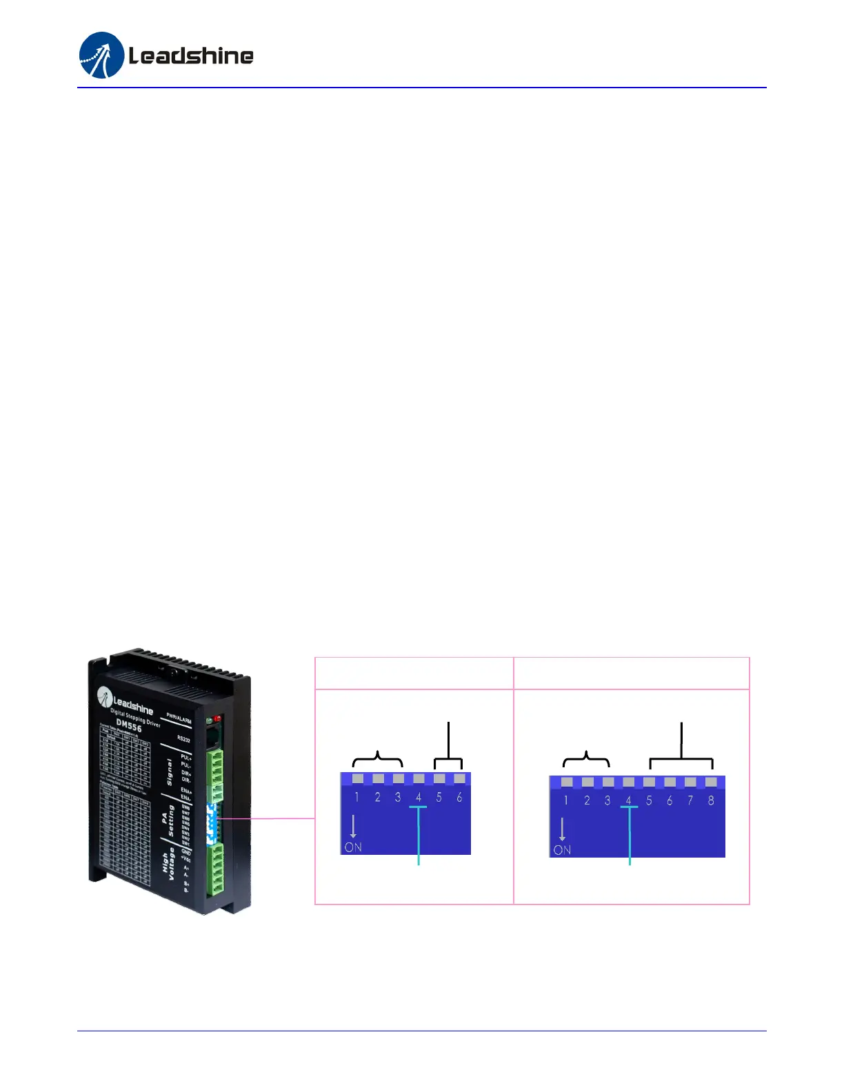
10. Configure the Drive
The DM drive uses a 6-bit or 8-bit DIP switch to set microstep resolution and motor operating current. When it’s not in software
configured mode, microstep resolutions and output current are programmable and set via the PC based software ProTuner. The user can
select more microstep resolution and current settings in software configuration mode than using the DIP switch. Please refer tot eh DM
drive’s software manual for the detail.
Dynamic Current
Microstep Resolution
Idle-Current
Dynamic Current
Microstep Resolution
Idle-Current
8-bit DIP Switch 6-bit DIP Switch
10
‐
‐