Digital Stepper Drive Hardware Installation Manual
Elimination of Heat
Drive’s reliable working temperature(heat sink) should be <70℃(158℉), and motor working temperature(surface) should be
<80℃(176℉);
It is recommended to use automatic idle-current mode, namely current automatically reduce to 60% when motor stops, so as to
reduce driver heating and motor heating;
It is recommended to mount the driver vertically to maximize heat sink area. Use forced cooling method to cool the system if
necessary.
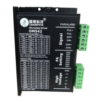
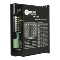
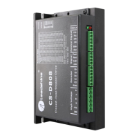
3. Connectors and Pin Assignment
The DM stepper drives have two connectors, connector for control signals connections and connector for power and motor connections.
Most DM drives adopt screw terminals for signal and power connections like follows. Please refer to drive’s datasheet for the detail.
Signal Connector, 4-pin + 2-pin screw terminal, 3.81 mm space
Signal Connector, 4-pin screw terminal, 3.81 mm space
Power Connector, 6-pin screw terminal, 3.81 mm space
4. Control Signal Requirement
Signal Mode and Sequence Chart
Most DM drive can support Pulse/Direction and CW/CCW control signal modes. In order to avoid some fault operations and deviations,
PUL, DIR and ENA should abide by some rules, shown as following diagram:
3
‐
‐