DM542 Fully Digital Stepper Drive Manual DM542 Fully Digital Stepper Drive Manual
3 4
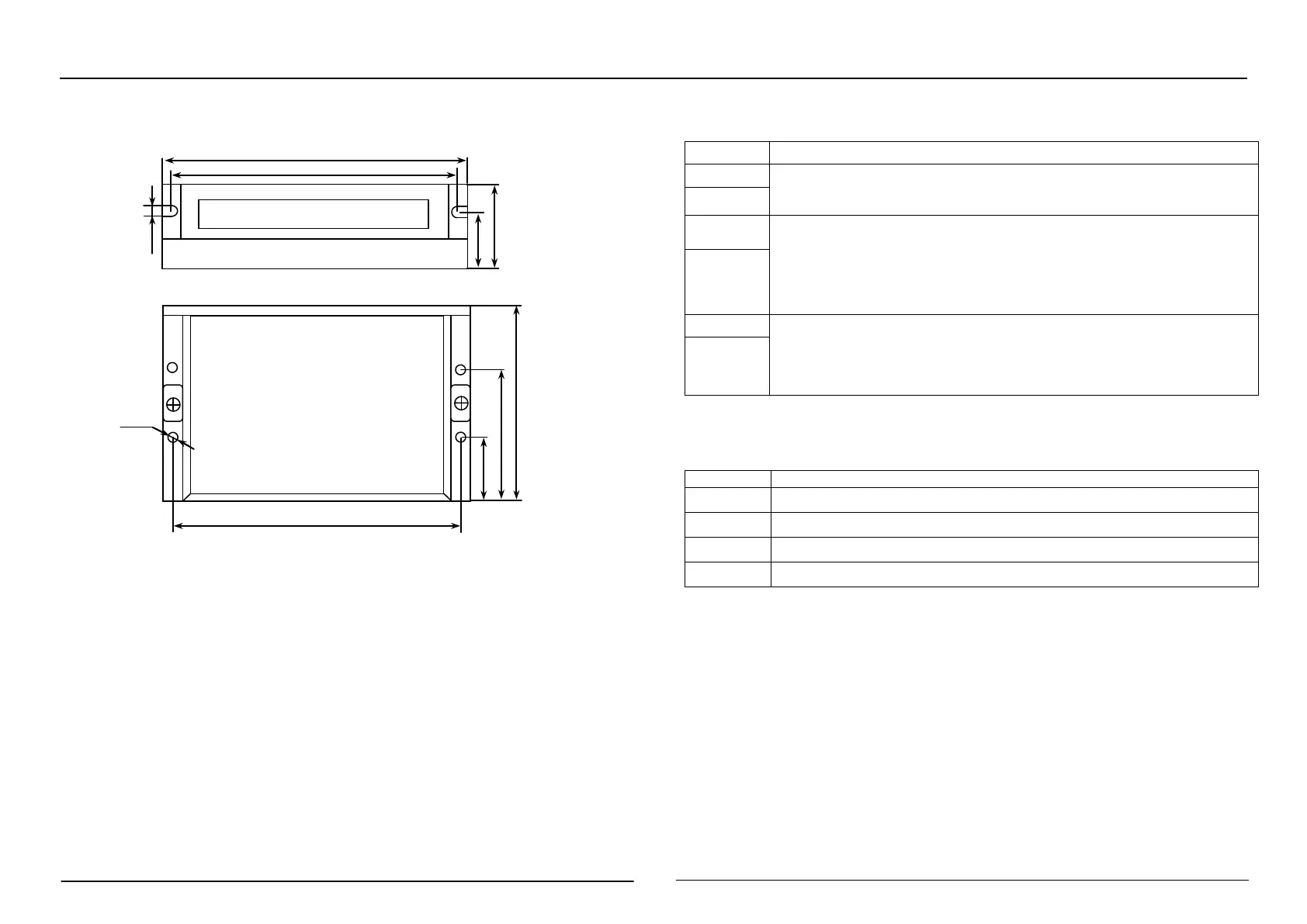
3. Mechanical Specifications (unit: mm [inch])
*Recommend use side mounting for better heat dissipation
4. Elimination of Heat
1)Driver’s reliable working temperature should be <70℃(158℉), and motor working
temperature should be <80℃(176℉);
2)It is recommended to use automatic idle-current mode, namely current automatically reduce to
50% when motor stops, so as to reduce driver heating and motor heating;
3)It is recommended to mount the driver vertically to maximize heat sink area. Use forced cooling
method to cool the system if necessary.
Pin Assignment and Description
1. Pin Assignment
1
Control signal interface
PUL+
Pulse signal: pulse rising edge is valid; PUL is 4.5~28Vdc at high level and 0~0.5V
at low level. In order to respond reliably to pulse signals, the pulse width should be
μ
。
PUL-
DIR+
Direction signal: High/low level signal. To ensure reliable commutation of the
motor, the direction signal should be established before the pulse signal is at least
2μs. The initial running direction of the motor is related to the wiring of the motor.
Interchanging any phase winding (such as A+, A-exchange) can change the
direction of the initial running of the motor. DIR is 4.5~28Vdc at high level and
DIR-
ENA+
Enable signal: This input signal is used to enable or disable. When ENA+ is
connected to 4.5~28Vdc, when ENA- is connected to low level (or internal
optocoupler is on), the driver will cut off the current of each phase of the motor to
make the motor free, and the stepping pulse will not be responded. When this
function is not needed, the enable signal terminal can be left floating.
ENA-
2
Connector Configurations
GND
Power supply, 20~50 VDC, Including voltage fluctuation and EMF voltage.
+Vdc
Power Ground.
A+、A- Motor Phase A
B+、B-
Motor Phase B
3
Status indication
The green LED is the power indicator. When the driver is powered on, the LED is always on; when
the driver is powered off, the LED is off. The red LED is a fault indicator. When a fault occurs, the
indicator flashes in a cycle of 3 seconds. When the fault is cleared by the user, the red LED is
always off. The number of flashes of the red LED in 3 seconds represents different fault
information, as shown in the following table:
Figure 1: Mechanical specifications