DM542 Fully Digital Stepper Drive Manual DM542 Fully Digital Stepper Drive Manual
11 12
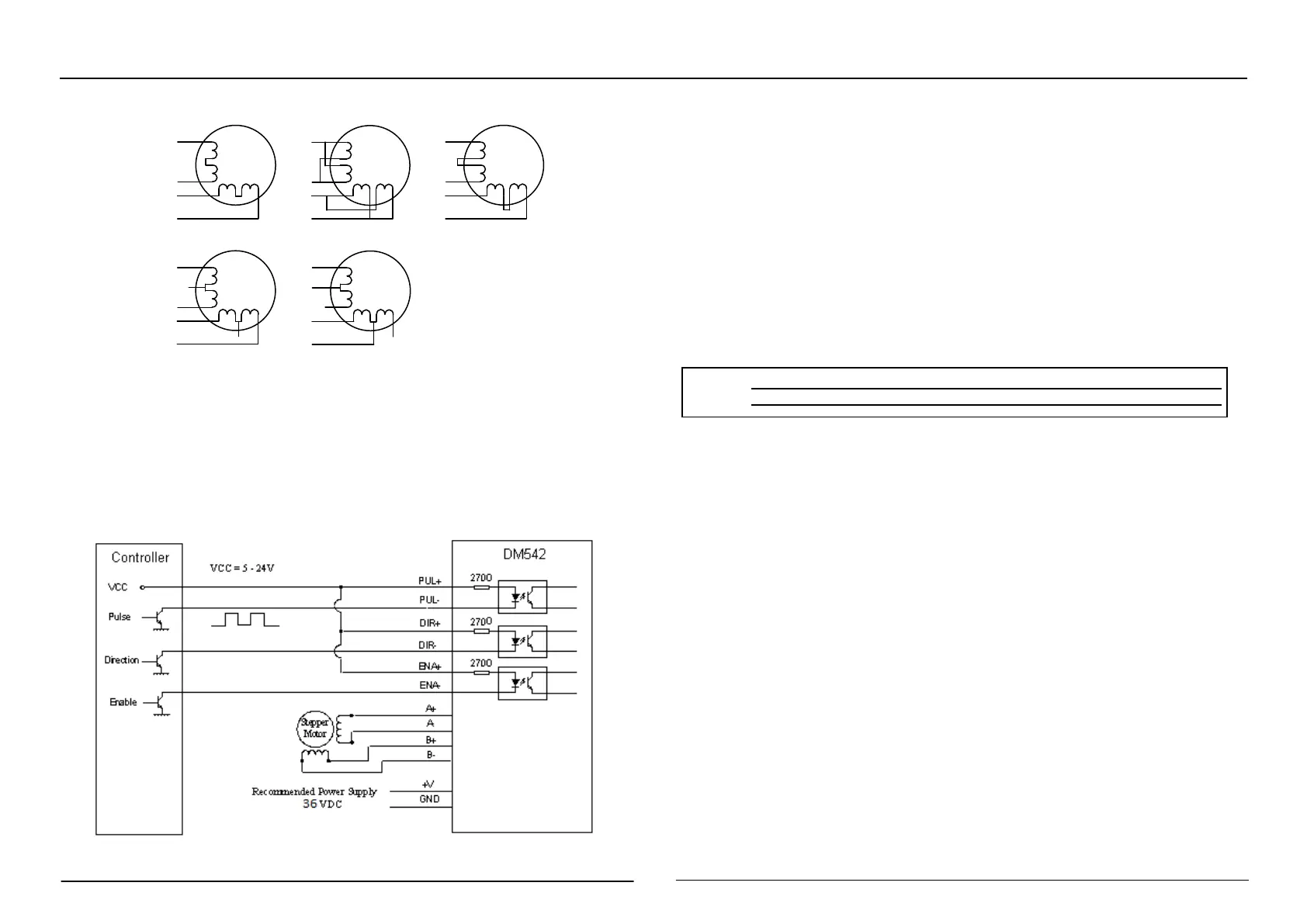
3. Typical Connection
1
Typical Connection
A complete stepping system should include stepping motor, stepping driver, power supply and
controller (pulse generator). A typical connection is shown
Typical connection
Protective function
1) Short circuit protection
When a phase-to-phase short circuit occurs or an internal overcurrent occurs in the driver, the
red light of the driver flashes once and blinks repeatedly within 3 seconds. At this point, the fault
must be discharged and the power-on reset should be resumed.
2) Overvoltage protection
DM542 When the input voltage is higher than 60V, the red light of the driver flashes twice,
and it flashes repeatedly within 3 seconds. At this point, the fault must be discharged and the
power-on reset should be resumed.
3) Motor open circuit protection
When the motor is open or not connected, the drive driver flashes red 4 times and flashes
repeatedly within 3 seconds. At this point, the fault must be discharged and the power-on reset
should be resumed.
△
Note: Since the drive does not have the reverse polarity protection function of
the power supply, please confirm the correct connection between the positive
and negati e terminals of the po er s ppl before po ering p Re ersing the
8-lead motor parallel
connections
8-lead motor series connections
6-lead motor full coil (higher
torque) connections
6-lead motor half coil (higher
speed) connections