The LEDS are arranged in one row of 8.
The left hand 4 LEDs relate to the input sources 1 to 4 from left to right.
The right hand 4 LEDs relate to the output zones 1 to 4 from left to right.
Green LEDS indicate actively switched inputs and outputs.
Cyan LEDs indicate exclusive source (zone lock) switched inputs and outputs.
Blue LEDs indicate a switching function or a supervisory function in progress.
The 2 press buttons can be used for manual source to zone selections and other
special functions.
See sections 5.2 to 5.4 for further information on the LEDs and press button switches.
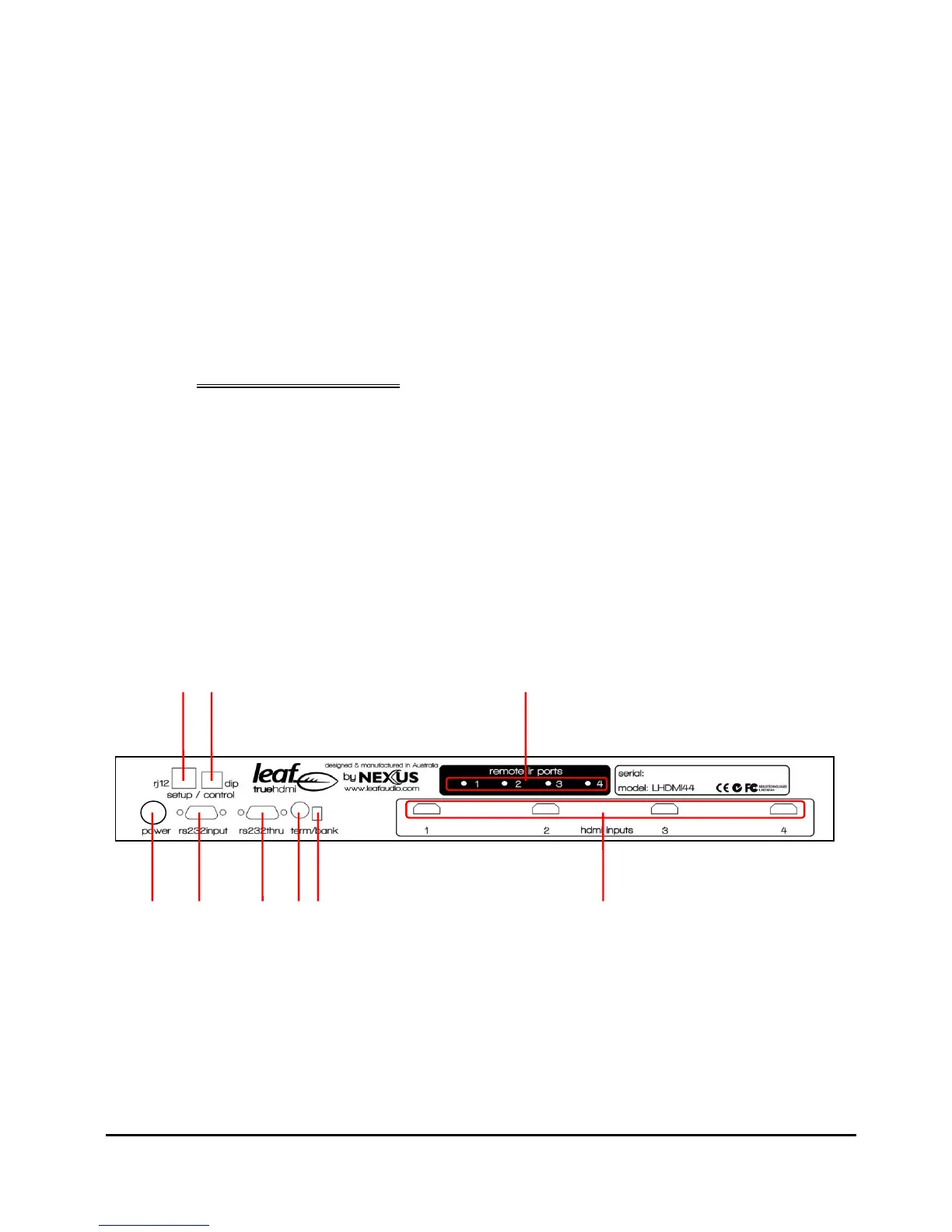
2 Rear panel layout:
The LHDMI44 rear panel has the following fittings as depicted below.
1. 1 x RJ12 type Leaf Control input port
2. 1 x 4 way Dip Switch module
3. 4 x 3.5mm Tip Ring Sleeve sockets for connection of IR devices
4. 1 x 4 pin DIN Power connector receptacle
5. 1 x RS232 serial control input connector
6. 1 x RS232 serial control out connector
7. 1 x 16 position rotary Bank Select switch
8. 1 x RS232 Terminate switch
9. 4 x HDMI Input or source ports.