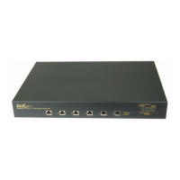
2.6 RS232 Serial Control connectors
The unit can be controlled by serial commands through the RS232 input port. Typically
this would be connected to a control system with a straight through DB9 Male to
Female RS232 lead. Some control systems may require only the TxD, RxD and Gnd
wires of an RS232 lead to be connected. The pin configurations of these 3 connections
on the DB9 plug is: TxD = Pin 2, RxD = Pin3, Gnd = Pin5.
2.6.1 Single LHDMI66 use
The RS232 Input port is used for controlling the unit.
The TERM (Termination) switch (ref: para 2.8) must be set to ON (Up).
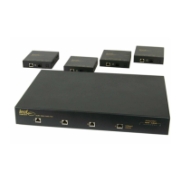
2.6.2 Multiple LHDMI66 use
Multiple units can be chained together and addressed on the same RS232 link
by connecting the RS232 thru (out) port on one unit to the RS232 input port of
the next unit.
The last unit in the chain must have the TERM (Termination) switch (ref:para 2.8)
set to ON (Up), while all other units in the chain must have this switch set to OFF
(Down). The RS232 Input port is used for controlling the units.
2.7 Bank Select Switch
The 16 position rotary BANK switch selects the RS232 bank address for the unit
as per the following Bank Select Table.
LHDMI66 OUTPUT ADDRESS
(ZONE NUMBER)
Table 2: BANK SELECT TABLE