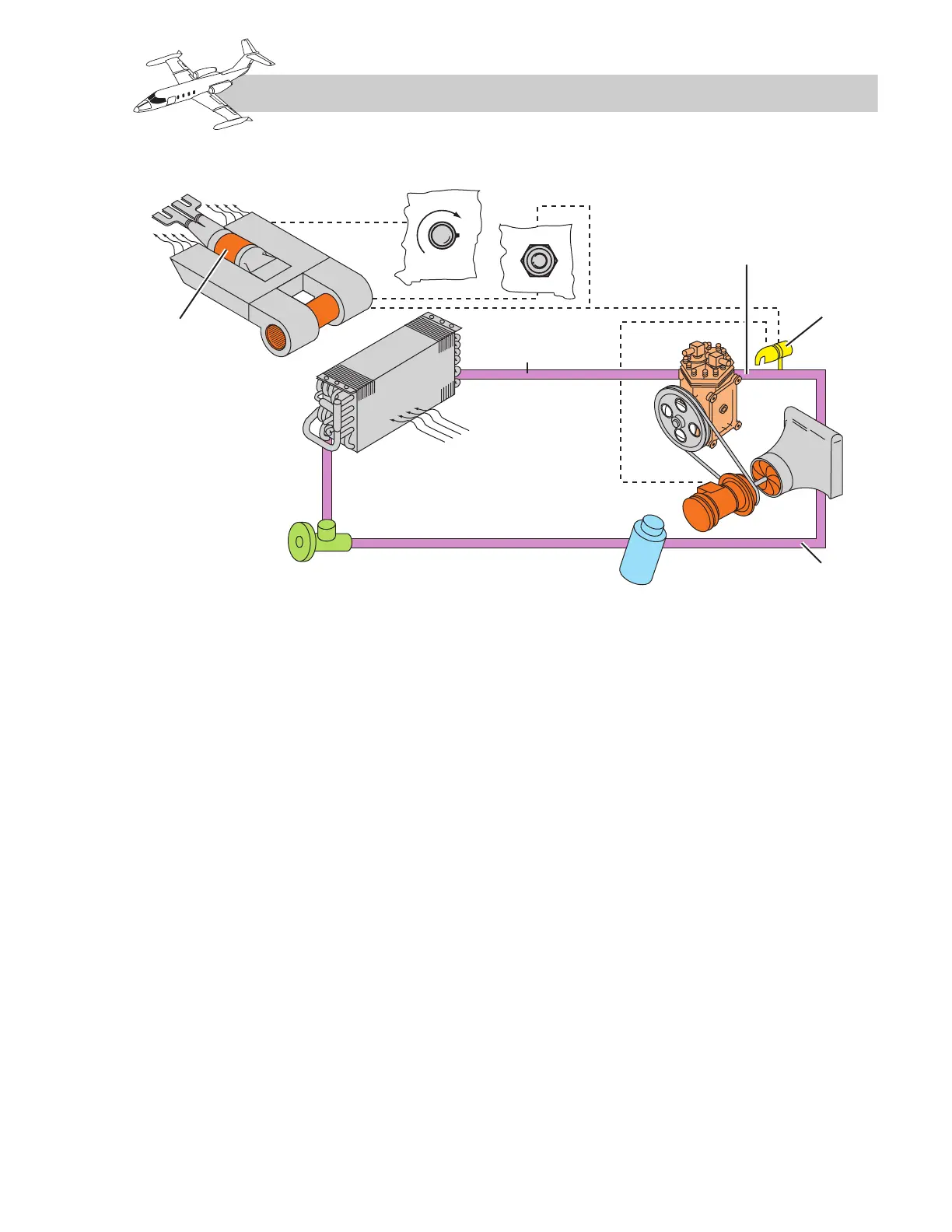
Figure 11-18. Auxiliary Cooling System
System components include the compressor
motor, compressor, condenser, receiver-
dehydrator, evaporator and blower, and the
control switch.
The compressor motor has a 3 3/4-hp rating
at 7,000 rpm. The motor requires no external
cooling and receives 28-VDC power through
a 150-ampere current limiter in the tailcone to
drive the compressor via a V-belt unit.
The compressor is a two-cylinder unit with a
pressure switch plumbed to the compressor dis-
charge port. If the discharge pressure reaches
approximately 335 psi, the switch contacts open
and deenergize the compressor motor. When
the pressure drops to 205 psi, the switch con-
tacts again close, reenergizing the compressor
motor. Operation of this pressure switch does
not affect the fan operation. The refrigerant
condenser is a plate and fin unit. High-pressure,
high-temperature vapor enters the condenser
from the compressor. This vapor is then cooled
by the air passing over the condenser surface and
changes to liquid. Heat from the condenser is
removed by a fan mounted on the compressor
motor shaft. The receiver-dehydrator removes
the small traces of moisture that may remain in
the system. A sight glass for observing refrig-
erant flow is installed in the tip of the receiver-
dehydrator. If the sight glass is generally clear
and performance is satisfactory, occasional
bubbles do not indicate refrigerant shortage.
The evaporator is installed to cool, dry, and,
through filtration, clean the air in the cabin
section. Refrigerant enters the evaporator from
the expansion valve as a low-pressure mixture
of liquid and vapor. The liquid vaporizes at this
low pressure, absorbing large quantities of
heat from the air that passes through the
evaporator fins, thus cooling the air being
recirculated by the cabin blower. As heat is
transferred through the walls of the evapora-
tor from warm air passing over them, moisture
in the air condenses and is drained overboard.
The Freon system is manually controlled with
the COOL SYS–OFF–FAN switch (Figure
11-17) located on the climate control panel.
11-15
FOR TRAINING PURPOSES ONLY