EMERGENCY LIGHTING
General
On airplanes Models 24-255 and subsequent,
25-090, and 25-094 and subsequent, and those
modified by AAK 73-6, emergency cabin light-
ing is provided by utilizing the upper central
panel lights. If a depressurization condition
should occur, the oxygen system aneroid
switch completes a 28-VDC circuit to the de-
pressurization relay control circuit. The con-
trol circuit causes the upper center panel lights
to illuminate regardless of light control switch
position. An optional emergency exit and wing
inspection lighting system may be installed to
provide emergency lighting.
Egress Lighting
General
If the optional emergency lighting package is
installed, the airplane is equipped with two
emergency exit and wing inspection power
supplies. Each power supply consists of two
sealed nickel-cadmium batteries and a control
circuit module. One power supply is installed
in the left service cabinet. The second power
supply is located on the cabin floor beneath the
divan seat. The wing inspection light is in-
stalled on the right side of the airplane adja-
cent to the lower forward corner of the
emergency exit window. The emergency exit
light is installed in the upper cabin door. The
light illuminates the lower cabin door and the
immediate area around the door. The cold
cathode lights on the right side of the upper
center panel and the optional forward left and
right upper center panel lights are powered by
the emergency battery.
Control
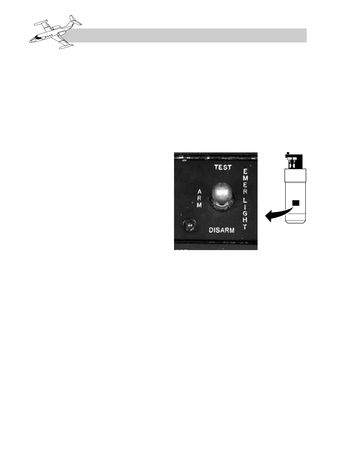
The EMER LIGHT TEST switch (Figure 3-5)
provides the test function for the system and for
automatic illumination of the emergency lights
in the event of an interruption of normal DC elec-
trical power. The switch has three positions:
TEST, ARM, and DISARM. Setting the switch
to TEST simulates a failure of normal DC elec-
trical power and illuminates the upper cabin
entry door light, the emergency exit light, and
the cabin overhead lights. Setting the switch to
ARM will arm the system to illuminate the
emergency lights in the event of a failure of
normal DC electrical power. With power on the
airplane, setting the switch to DISARM iso-
lates the emergency lights from the emergency
batteries. The switch should be set to ARM
prior to takeoff. If the switch is in the DISARM
position and at least one BAT switch is on, the
amber light adjacent to the switch will illumi-
nate to remind the pilot that the switch should
be set to ARM. The switch should be set to DIS-
ARM prior to setting the BAT switches to OFF.
The WING INSPECTION light switch (in-
cluded as part of the emergency lighting sys-
tem), located adjacent to the EMER LIGHT
TEST–ARM–DISARM switch, may be used in-
dependently of the emergency lighting system
to visually check for ice accumulation on the
right wing leading edge. Turning the switch on
illuminates the exterior wing inspection light.
EXTERIOR LIGHTING
GENERAL
The exterior lighting systems consist of the
landing–taxi lights, navigation lights, anticol-
lision lights, recognition lights, strobe lights, and
an optional right wing inspection light (Figure
3-6). The exterior lighting switches are located
on the instrument panel (Figure 3-7).
3-4
FOR TRAINING PURPOSES ONLY