INTRODUCTION
This chapter describes the powerplant installed on Learjet 20 series airplanes. In addi-
tion to the powerplant, the chapter describes such engine-related systems as oil, fuel,
ignition, engine controls and instrumentation, engine synchronization, and the Dee
Howard thrust reversers.
GENERAL
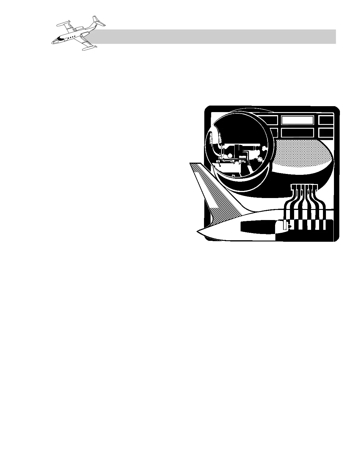
The airplane is powered by two General
Electric, CJ610 single rotor, axial-flow turbo-
jet engines. The engines are installed in pylon-
mounted nacelles. The engine assembly
consists of an eight-stage, axial-flow com-
pressor, driven by a two-stage turbine, an an-
nular combustion section, and a fixed-area
concentric exhaust cone. Each engine is at-
tached to the engine beam at three attachment
points. Eight thermocouples generate an av-
erage value of exhaust gas temperature, indi-
cated on the EGT gages in the cockpit. An
engine-driven starter-generator is installed on
each engine to provide engine starting and
furnish DC power to the airplane’s electrical
system. Compressor discharge air (bleed air),
through a mainframe port on each engine, is
utilized for cabin pressurization and cabin
heating, windshield defogging, wing anti-ice,
engine front frame anti-icing, and, on models
24-297 and subsequent and 25-135,
-181, and subsequent, for hydraulic reservoir
pressurization. On 24-350, -352, and subse-
quent and 25-227 and subsequent, bleed air is
also used for windshield/radome alcohol and
cabin temperature/pressurization control.