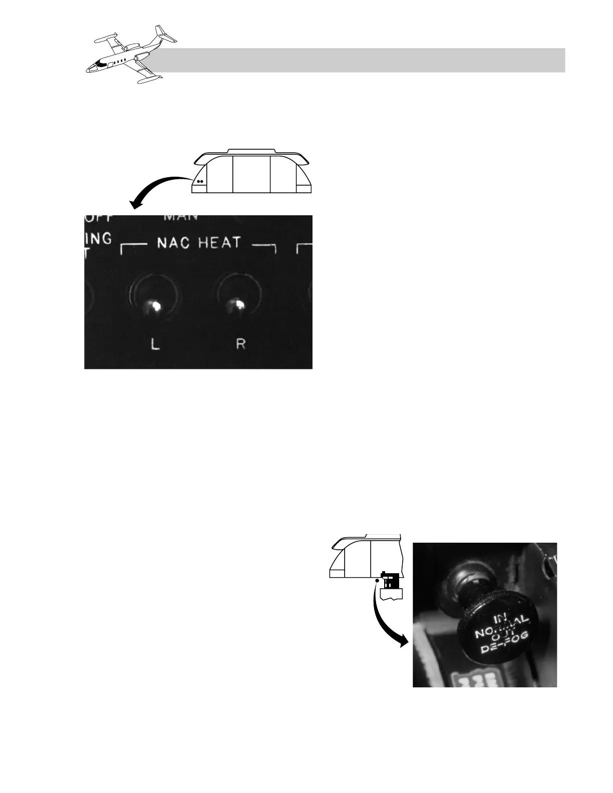
Each engine anti-ice system is independently
controlled by the L and R NAC HEAT switches
(Figure 10-5) located on the anti-ice control panel.
When a NAC HEAT switch is turned on, elec-
tric power is supplied to heat the nacelle lip.
This is done by energizing a nacelle heat relay
which allows 28 VDC to flow from the gen-
erator bus to the nacelle heating elements.
Each nacelle requires 50 to 60 amperes.
Simultaneously, power is removed from the en-
gine anti-ice valve allowing bleed air to flow
through the hollow inlet guide vanes, vari-
able inlet guide vanes, and the engine nose
cone. The bleed air is discharged into the inlet,
where it reenters the engine. This heated air,
being less dense, causes a decrease in the en-
gine pressure ratio (EPR).
Engine Ice Lights
The amber L and R ENG ICE lights on the
glareshield annunciator panel (see “Annunciator
Panel” section) provide a visual indication of
insufficient bleed-air pressure for adequate
front frame anti-ice protection. A pressure
switch on the front frame actuates and causes
illumination of the lights whenever bleed-air
pressure drops to less than 5 psi. On the ground,
approximately 70% rpm is required to extin-
guish the lights.
Inlet Heater Light
A temperature-sensing switch is located in the
nacelle on each engine to detect a possible
overheat condition. A single amber INLET
HTR light (see “Annunciator Panel” section) on
the glareshield illuminates when either nacelle
reaches 190 ±3ºF and extinguishes at 180ºF.
This light is connected through the squat switch
relay box subsequent to SNs 24-209 and 25-045
so that it does not illuminate in flight. If the
INLET O’HEAT light illuminates on the ground,
the NAC HEAT switches must be turned off.
WINDSHIELD ANTI-ICE/DEFOG
AND RAIN REMOVAL SYSTEM
General
The windshield heat system utilizes bleed air for
defogging, rain removal, and anti-ice protection.
The windshield heat/defog system (Figure 10-6)
can be controlled either automatically or manu-
ally. The system is also used to supplement cock-
pit heating through the pilot’s footwarmers and
to provide an alternate bleed-air source for
emergency pressurization.
An IN NORMAL/OUT DE-FOG knob located
below the instrument panel to the left of the
pedestal (Figure 10-7) controls a two-way
valve within the ducting which directs bleed
air to the windshield or cockpit footwarmers.
10-5
FOR TRAINING PURPOSES ONLY