Fuel Pressurizing and
Drain Valve
The pressurizing valve includes a sliding
spring-loaded piston and a Teflon seat. A means
is provided to bring centrifugal pump pres-
sure to the backside of the piston so that valve
opening is a function of fuel pressure plus
spring force. Simultaneously, fuel is discharged
to the left and right manifolds. The drain valve
is a spring-loaded piston-type valve, which is
spring-loaded to the open position and is closed
by fuel pressure (60–100 psi).
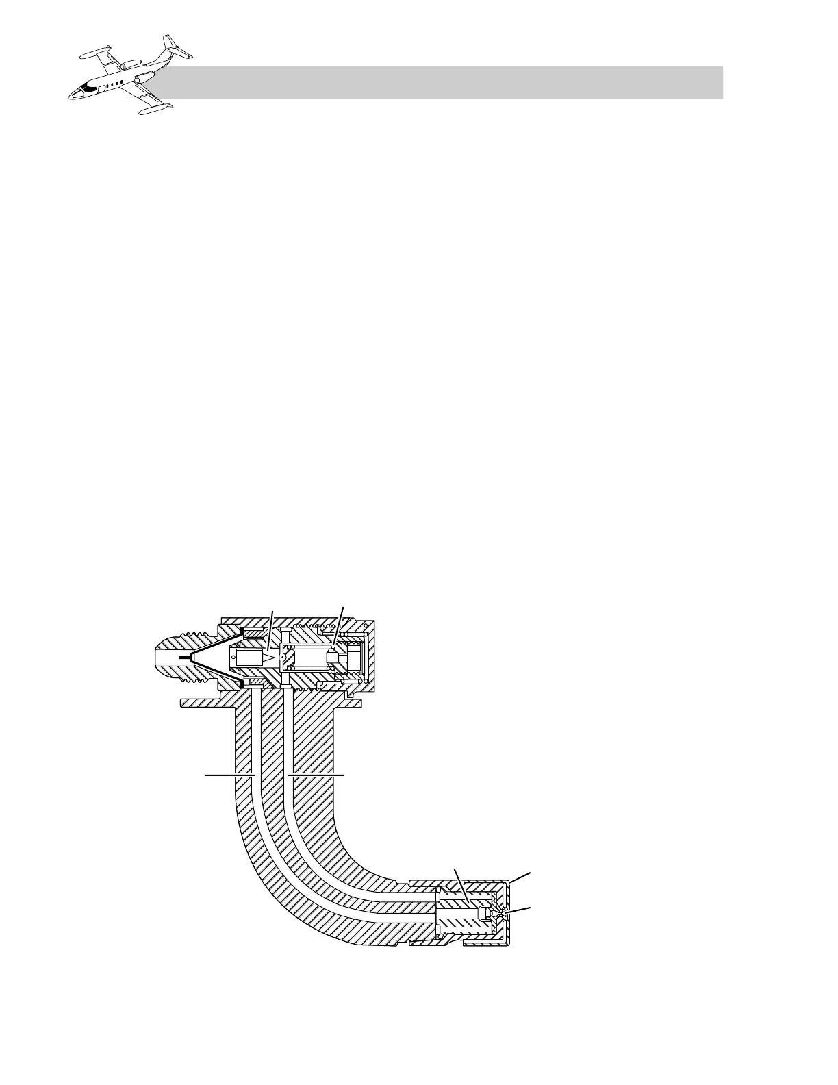
Fuel Nozzles
Twelve fuel nozzles provide the correct spray
pattern of metered fuel to the combustion sec-
tion for the entire operating range of the en-
gine. Each fuel nozzle has two major
sections—the flow divider and the nozzle
(Figure 7-10). The flow divider housings are
attached to pads on the mainframe which re-
tain the nozzles in position in the combustion
section. This housing has a fuel inlet port
which is connected to the fuel manifold, and
two outlet ports which supply fuel to the noz-
zle section through two tubes—the primary and
secondary fuel nozzles tubes. The air-cooled
nozzles section contains a primary and second-
ary orifice. The initial flow of fuel into the fuel
nozzle passes through the divider housing and
the primary fuel tube to the primary nozzle ori-
fice where the spray pattern is formed for
combustion.
As fuel pressure increases, fuel is allowed to
flow through the secondary fuel tube and noz-
zle orifice as well as the primary, forming an-
other spray pattern to supplement the fuel
requirements. During engine operation, the
primary flow remains constant, and the sec-
ondary spray flow increases to satisfy engine
operating requirements.
Fuel Drain Collector
A collector tank is installed to collect and re-
tain the fuel drained from the fuel manifold and
flow dividers through the drain section of the
pressurizing and drain valve during engine
shutdown. The canister volume is sufficient to