The system should be off below 70% rpm.
The indicator light will light if the system is
inadvertently left on with the landing gear
down. The control box senses pulse differ-
ence from the pickups, then energizes the
throttle cable actuator on the right (slave) en-
gine. The right engine rpm is matched to the
left (master) engine. The actuator travel is
limited; hence, the engines must be nearly
synchronized manually before setting the
control switch to ON to obtain maximum
±slave engine adjustment in synchroniza-
tion. The system operates on 28 VDC sup-
plied through a 7.5-amp circuit breaker
labeled “ENG SYN” on the copilot’s circuit-
breaker panel.
SYNCHROSCOPE (OPTIONAL)
Manual engine synchronization can be moni-
tored with the dual-engine synchroscope. The
synchroscope is basically a synchronous motor
driven by outputs from the tach generators and
is otherwise independent of the airplane electri-
cal system. A wheel marked by black and white
sections moves clockwise or counterclockwise
at a rate proportional to the difference in fre-
quency of the tach generators. Clockwise rota-
tion is for the right tach fast, and counterclock-
wise is for the left tach fast. Synchronization is
accomplished by adjusting either engine thrust
lever until the wheel stops rotation.
THRUST REVERSERS
(OPTIONAL)
GENERAL
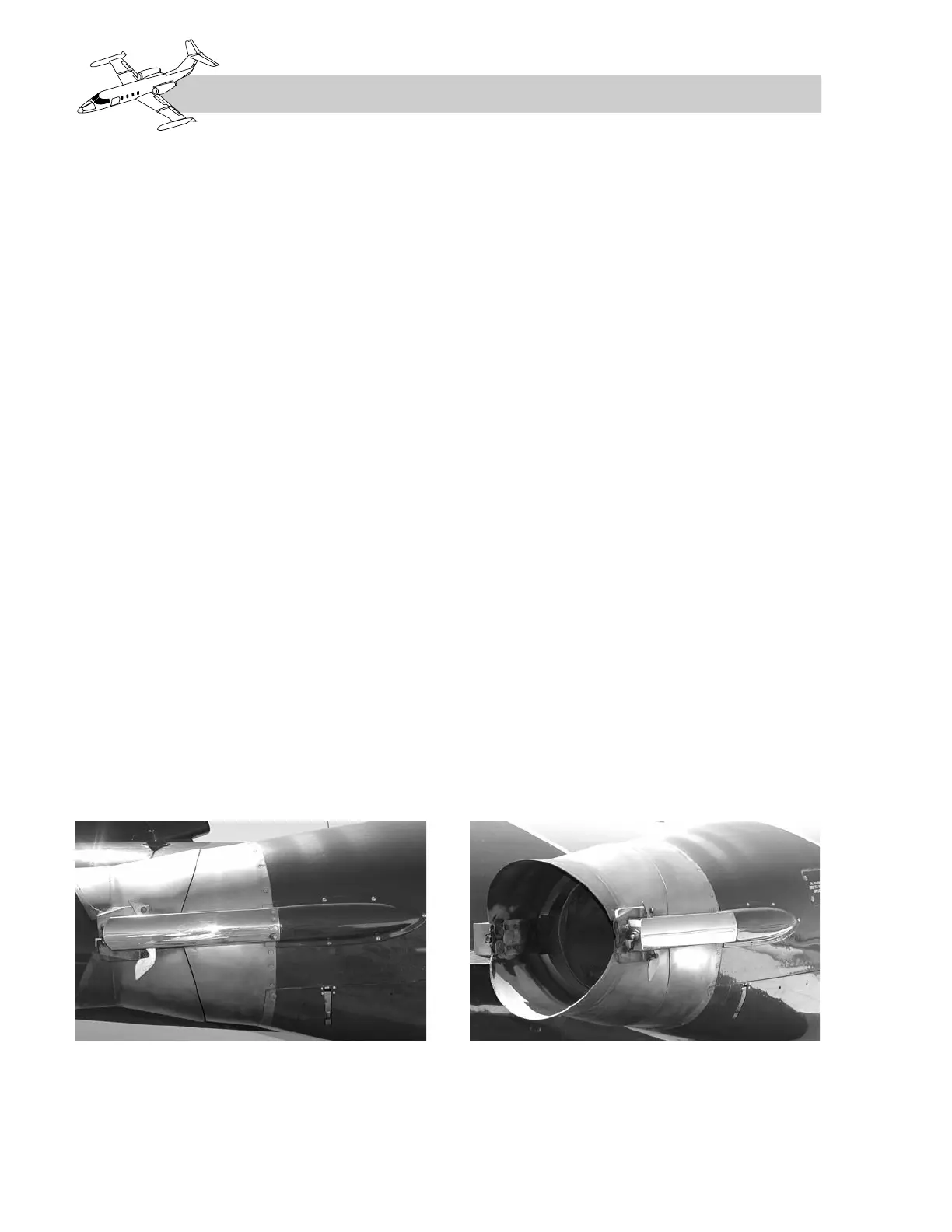
The thrust reversers (Figure 7-15) are an ad-
ditional deceleration system which may be
used anytime the airplane is on the ground
to produce shorter stopping distances. They
cannot be used to supersede runway length
requirements published in the performance
chapter of the AFM.
Each engine is equipped with a target thrust
reverser (T/R) consisting of upper and lower
clamshell doors (buckets), pivoted near the
engine centerline. The reverser doors are hy-
draulically actuated, and electrically con-
trolled mechanical latches are provided for
each engine to secure the doors in the stowed
position. Hydraulic pressure for the system is
supplied by the airplane hydraulic system
through a one-way check valve. The T/R sys-
tem includes an accumulator. When fully
charged, the accumulator hydraulically pro-
vides several cycles should the airplane hy-
draulic system fail upstream of the one-way
check valve. The accumulator is serviced to
650 psi with dry air or nitrogen (hydraulic
pressure zero).
Figure 7-15. Thrust Reversers