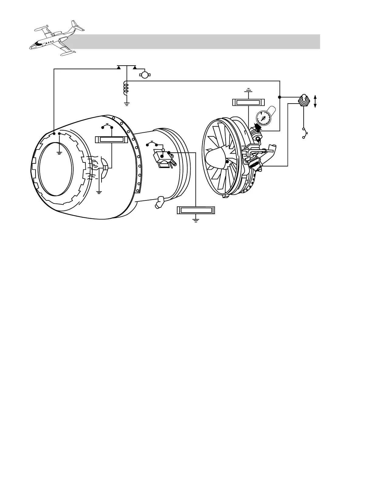
Engine Anti-ice Control Valve
The engine anti-ice control valve is located on
the left forward side of the engine. The valve
is spring-loaded to the open position. In order
to keep the valve in the closed position, 28
VDC and bleed-air pressure are required. If
electrical power is lost, the spring in the valve
causes the valve to open. Therefore, during an
electrical power failure, the valve opens and
allows bleed air to flow to the front frame and
vanes. With the NAC HEAT switch in the OFF
position, 28 VDC is applied to the anti-ice
control valve solenoid and directs air pres-
sure to close the valve.
Engine Ice Light
The anti-ice pressure switch is located down-
stream of the anti-ice control valve. Whenever
the NAC HEAT switch is in ON and the pres-
sure in the front frame drops below 5 psi, a
circuit is completed that illuminates the amber
ENG ICE light (see “Annunciator Panel” section)
on the warning panel. Therefore, the ENG
ICE light only indicates insufficient bleed-air
pressure to the front frame. Adequate pressure
to the front frame requires approximately
70% rpm on the ground and at least 80% rpm
while airborne.
Electrical power for heating the nacelle lip is
provided by its respective generator. Loss of
a generator results in the loss of the associated
nacelle heat. Each nacelle uses approximately
50 amperes for heating.
A temperature-sensing switch is located in
the nacelle on each engine to detect a possi-
ble overheat condition. A single amber INLET
O’HEAT light on the warning panel illuminates
when either nacelle temperature reaches 210ºF.
The light extinguishes when nacelle temper-
ature decreases to 190ºF. If the light illumi-
nates in flight, it may be disregarded; however,
for ground illumination, nacelle heat must be
turned off.
10A-4
FOR TRAINING PURPOSES ONLY