From the bleed-air manifold, bleed air is
distributed to the flow control valve for pres-
surization and cabin heating.
Flow Control Valve
The flow control valve is a solenoid-operated
valve which controls and regulates the flow of
bleed air into the cabin. The position of the
valve is determined by the CAB AIR switch
(Figure 11-3).
Figure 11-3. CAB AIR Switch
When the CAB AIR switch is in OFF, the valve
is energized and closes. When the switch is
in ON, the valve is deenergized and opens. DC
power for its operation is drawn through the
AIR BLEED circuit breaker on the left es-
sential bus.
Other functions of the flow control valve and
the venturi located downstream of the flow
control valve are related to the pressurization
system. Those aspects of component operation
are discussed in Chapter 12, “Pressurization.”
Hot Air Bypass Valve (H-Valve)
The hot air bypass valve, more commonly
referred to as the “H-valve,” is located in the
bleed-air upstream of the heat exchanger. Its
function is to split the flow of bleed air,
directing some to the heat exchanger for cool-
ing and some to bypass the heat exchanger.
The result is a mixture of the two airflows,
thereby conditioning the bleed air before it
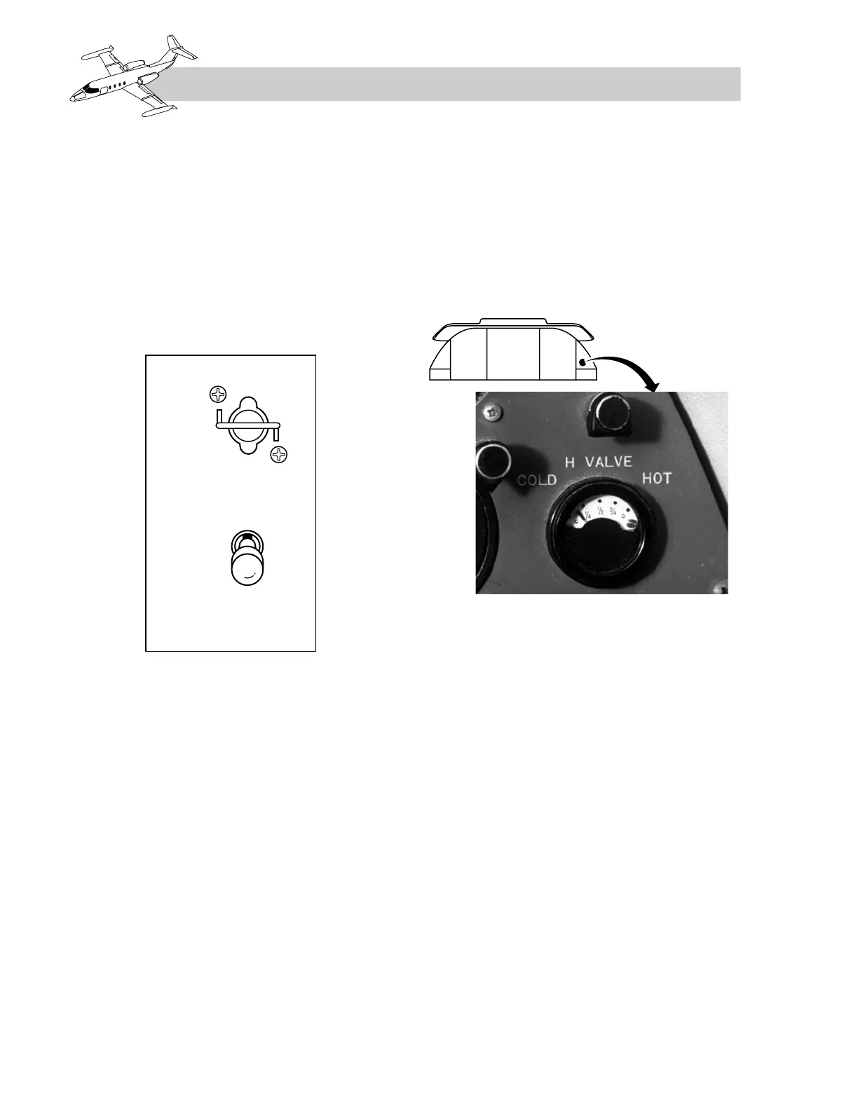
enters the cabin area. The position of the H-
valve is indicated on the H VALVE indicator
located on the copilot’s instrument panel
(Figure 11-4).
Figure 11-4. H VALVE Indicator
(Current Models)
The H-valve butterfly is positioned pneumat-
ically by servo bleed air (see Chapter 9) from
the climate control system. No electrical cir-
cuits are involved except that the H VALVE in-
dicator requires DC power. Approximately
five seconds is required for the valve to travel
from fully opened to fully closed. The valve
is spring-loaded to the full cold position any
time servo air pressure is not available.
Ram-Air Heat Exchanger
The heat exchanger is located inside the tail-
cone. It consists of a bleed-air core surrounded
by a ram-air plenum. Cool air enters the ram-
air inlet in the dorsal fin and flows through the
plenum, across the bleed-air core, thus cool-
ing the bleed air. The ram air then exhausts into
the tail compartment.
11-4
FOR TRAINING PURPOSES ONLY