Do you have a question about the Lectra Alys 120 and is the answer not in the manual?
Explains the manual's objective and intended audience.
Guides users on navigating the manual's sections and conventions.
Details symbols and notation used for warnings and advice.
Covers electrical hazards, including fuse replacement and operating voltage.
Explains how to check and adjust the plotter's operating voltage.
Guidelines for safe handling and storage of ink cartridges and paper.
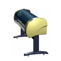
Overview of the Alys inkjet plotter and its main components.
Explains the functions and indicators of the plotter's control keyboard.
Specifies the required hardware and software for the operating PC.
Lists detailed technical specifications for the Alys plotter.
Steps to access and log into the advanced maintenance software.
Procedure for updating the plotter's electronics management program.
How to synchronize the plotter's internal clock with the PC clock.
Guides on accessing and conducting various diagnostic tests.
How to check and adjust plotter parameters using the software.
Covers tests for sensors, valves, relays, and motors.
Lists necessary tools and general safety advice for maintenance.
Provides essential safety and procedural advice before starting maintenance.
Introduces the plotter's main components and their locations.
Illustrates the front of the plotter and its parts.
Shows the left side of the plotter from the back.
Shows the right side of the plotter from the back.
Steps to remove the cover protecting the print heads.
Procedure for replacing the ink level sensor.
How to remove the buffer reservoir and its associated parts.
Instructions for correctly reinstalling the buffer reservoir assembly.
Instructions for safely removing the electronics board.
Guides on removing the combined head and buffer reservoir assembly.
Steps to remove the entire plotting block.
Steps for safely removing the plotter's side covers.
How to disconnect the ribbon cable from the command keyboard.
Identifies the Y motor and paper feed encoder on the left side.
Locates the fill pump and main electronics board on the left side.
Identifies the upward paper drive motor on the left side.
Detailed steps for removing and installing the fill pump tube.
How to remove shielding and disconnect board connectors.
Steps to remove the transformer base plate and earth braid.
Guides on unplugging, replacing, and reconnecting the transformer.
Procedure for replacing the Y motor, including belt and connector management.
Instructions for replacing carbon brushes in the motor assembly.
Steps for removing and installing the paper feed encoder unit.
How to adjust the height of the paper feed encoder roller.
How to remove shielding and disconnect encoder cables.
Steps to remove the pinion cover and dismantle the encoder.
Instructions for installing a new encoder and reassembling parts.
Procedure for replacing seals between print heads and suction system.
How to remove and mount carbon sliding contacts.
Steps to remove the Y carriage drive belt.
Instructions for removing and replacing the guide sockets.
How to position and install the drive belt on the Y carriage.
Procedures for adjusting belt tension after installation.
Detailed steps for adjusting the head drive belt tension.
How to adjust the short belt tension using a spring scale.
Instructions for greasing the block bearing spring.
How to grease the guide pins of the purge station.
How to connect the command keyboard and its ribbon cable.
Warnings about greasing rails and general cleaning advice.
Procedure for removing ink stains with a specific product.
Steps before handling the plotter, like checking the drain reservoir.