40
5.0 Status Monitor, Continued
745-573-B0-001 REV. A
The communication module installs in the same basic manner for all three levels of status monitoring.
The external connections will be different as defined in Section 4.3.
1. Turn off the CPR Unit, and remove AC Power.
2. Remove the communication module cover plate (if applicable).
3. Locate and pull out the ribbon cable with the connector, inside of the CPR Communicator
TM
module slot.
4. Plug in the ribbon cable connector into the PC board connector on the CPR Communicator
TM
module.
5. Insert the CPR Communicator
TM
module into the open slot on the CPR and secure with the two
mounting screws. Use caution when inserting so as not to “pinch” the ribbon cable between the
slot and the module. Refer to figure 4.1-1.
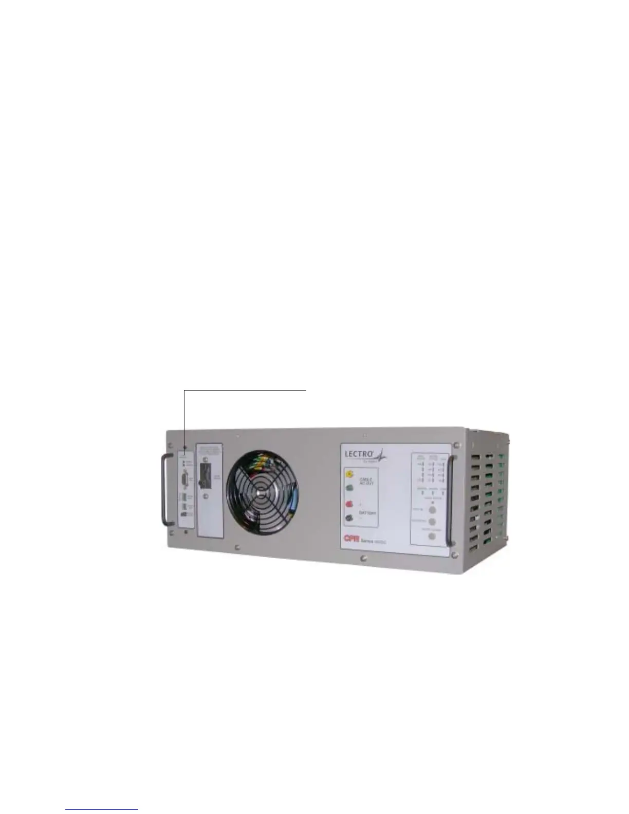
Communications Module
Fig. 5-1, CPR Unit, Showing Communicator Location
5.1 Installation