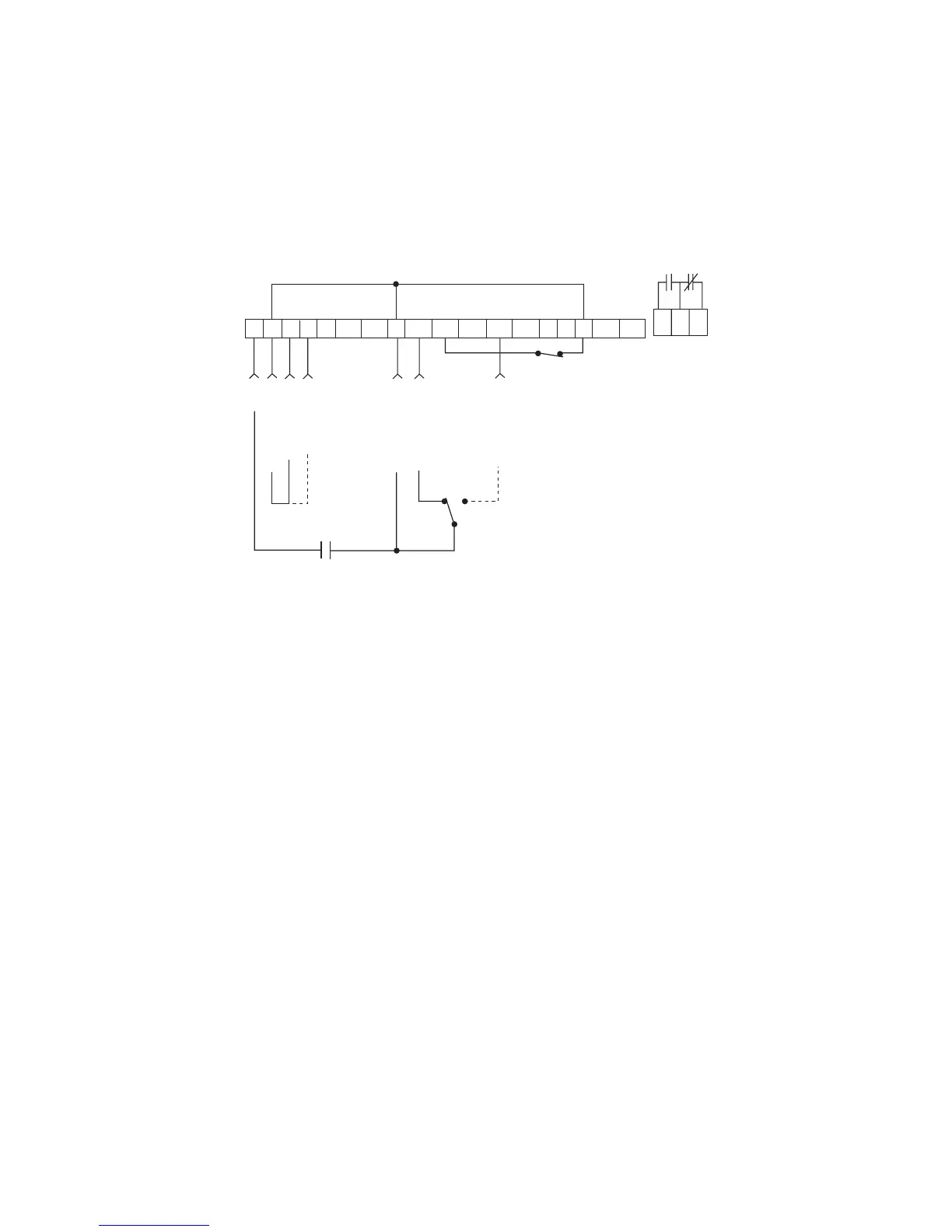
15.2 TWO-WIRE START/STOP CONTROL
Shown below is the wiring diagram for a typical two-wire start/stop control scheme, using one maintained
contact (such as that from a PLC) for START and STOP commands. Close the contact to START, and open
the contact to STOP. Also shown is the wiring for a 0-10 VDC or 4-20 mA speed reference signal.
NOTES:
1. Close TB-1 to TB-2 to RUN, and open to STOP.
2. If REVERSE direction is required, ROTATION must be set to FWD&REV, and TB-13C must be
set to START REVERSE (refer to Parameters: 27 - ROTATION, and 49 - TB13C).
3. Program TB-13A, 13B, or 13C to select the appropriate speed reference signal that will control the
drive speed (refer to Parameters 47, 48, and 49). When that TB-13 terminal is closed to TB-2, the
drive will respond to the selected speed reference signal. In the diagram above, TB-13A is programmed
to select either a 0-10 VDC or 4-20 mA signal.
4. If the contact closure is not made between TB-13A and TB-2 to select a speed reference, the drive will
default to MANUAL speed control, which is determined by Parameter 29 - MANUAL.
37