EasyManua.ls Logo

LEGRAND DPX3 630 User Manual

LEGRAND DPX3 630
27 pages
To Next Page IconTo Next Page
Page #1 background imageLoading...
Page #1 background image
Legrand Polska Sp. z o.o.
Infolinia: 801 133 084 lub +48 22 549 23 22
DPX
3
1600 wyłączniki z wyzwalaczem
termiczno-magnetycznym do 1250 A
oraz rozłączniki DPX
3
-I 1600
Nr referencyjne : 422 251/ 252/ 253/ 254/ 256/ 257/ 258/ 259/ 260/
261/ 263/ 264/ 265/ 266/ 268/ 269/ 270/ 271/ 272/ 273/ 275/ 276/ 277/
278/ 280/ 281/ 282/ 283/ 284/ 285/ 287/ 288/ 289/ 290/ 290/ 292/ 293/
294/ 295/ 296/ 297 & 422 490/ 491/ 492/ 493/ 494/ 495/ 496/ 497
1/10
Dokument : F01963PL/00 Aktualizacja : 06/10/2014 Data utworzenia : 06/10/2014
1. ZASTOSOWANIE
Wyłączniki i rozłączniki kompaktowe DPX
3
oferują optymalne
rozwiązania w zakresie zabezpieczania instalacji w obiektach
mieszkaniowych, użyteczności publicznej i przemysłowych.
2. ZAKRES OFERTY
36 kA TM
50 kA TM
70 kA TM
In
4P
3P+N/2
3P
4P
3P
4P
3P+N/2
630 A
4222 56
-
4222 63
4222 68
-
4222 75
4222 80
-
800 A
4222 57
-
4222 64
4222 69
-
4222 76
4222 81
-
1000 A
4222 58
4222 60
4222 65
4222 70
4222 72
4222 77
4222 82
4222 84
1250 A
4222 59
4222 61
4222 66
4222 71
4222 73
4222 78
4222 83
4222 85
100 kA TM
DPX
3
-I
In
3P
4P
3P+N/2
3P
4P
630 A
4222 87
4222 92
-
4224 90
4224 94
800 A
4222 88
4222 93
-
4224 91
4224 95
1000 A
4222 89
4222 94
4222 96
-
-
1250 A
4222 90
4222 95
4222 97
4224 92
4224 96
1600 A
-
-
-
4224 93
4224 97
3. WYMIARY
Otwory montażowe
3. WYMIARY (c.d.)
Widok frontowy, wykonanie stacjonarne (3P i 4P):
ZAWARTOŚĆ STRONA
1. ZASTOSOWANIE 1
2. ZAKRES OFERTY 1
3. WYMIARY 1
4. INFORMACJE OGÓLNE 2
5. DANE TECHNICZNE 2
6. ZGODNOŚĆ Z NORMAMI 3
7. WYPOSAŻENIE POMOCNICZE 3
8. CH-KI CZASOWO-PRĄDOWE 5

Other manuals for LEGRAND DPX3 630

Question and Answer IconNeed help?

Do you have a question about the LEGRAND DPX3 630 and is the answer not in the manual?

LEGRAND DPX3 630 Specifications

General IconGeneral
Rated current In630 A
Poles description3P, 4P
Breaking capacity Icu50 kA
Frequency50/60 Hz
StandardsIEC 60947-2
Rated ultimate short-circuit breaking capacity50 kA
Breaking capacity Ics37.5 kA
Rated service short-circuit breaking capacity37.5 kA
Protection degreeIP20

Summary

Product Application

Range of Offer

Product Dimensions

Front View - Stationary Version

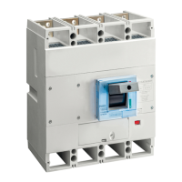
Front view with dimensions for 3P and 4P stationary versions.

General Product Information

Standard Equipment Details

Details on standard flat screw terminals and insulating barriers.

Mounting Options and Positions

Describes vertical, horizontal, and power switching mounting positions.

Technical Data

Circuit Breaker & Disconnector Specifications

Detailed technical specifications for DPX3 circuit breakers and DPX3-I disconnectors.

Circuit Breaker Construction Elements

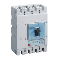
Diagram identifying key components of the circuit breaker.

Performance Data and Conditions

Breaking capacity, rated current, power loss, and operating conditions.

Derating Factors and Special Network Operation

Derating for temperature, altitude, 400Hz, and DC networks.

Compliance with Standards

Designations and Symbols

Explanation of symbols and designations used in the document.

Auxiliary Equipment

Protection and Release Devices

Details on residual current protection and types of releases.

Control and Signaling Contacts

Specifications for auxiliary and alarm contacts.

Operating Mechanisms

Information on rotary and motor drives for switch operation.

Connection Accessories

Terminal shrouds, crimp blocks, and busbar extensions.

Slide-out Version Execution

Slide-out Base and Mechanism

Base and mechanism for converting to slide-out version.

Sliding Mechanism Key Locks

Key locks for securing the sliding mechanism.

Slide-out Mechanism Accessories

Accessories for the sliding mechanism, including handles and contacts.

Performance Characteristics

Time-Current Curves (up to 800 A)

Time-current curves for thermal-magnetic trip units up to 800A.

Time-Current Curves (1000-1250 A)

Time-current curves for thermal-magnetic trip units from 1000-1250A.

I²t Energy Limitation Characteristic

Graph showing I²t energy limitation for different current ranges.

Limited Current Characteristic

Graph showing limited current (Ip) vs. short-circuit current (Icc).

Automatic Control Unit Wiring and Parameters

Wiring Diagram

Schematic diagram for the automatic control unit.

Parameter Setting Guide

Guide to setting parameters for the automatic control unit.

Manual Operation Modes

Automatic vs. Manual Mode Selection

Explanation of automatic and manual modes and selector operation.

Manual Operation Procedure

Step-by-step guide for performing manual operations.

Switch Operation Procedures

Closing Operation

Diagram illustrating the process of closing the switch.

Opening Operation

Diagram illustrating the process of opening the switch.

Reset Operation After Trip

Diagram illustrating the reset procedure after a trip event.

Installation and Assembly Steps

Cover Removal and Diaphragm Drilling

Instructions for removing covers and drilling diaphragms.

Nameplate Application

Procedure for applying the nameplate.

Component Installation

Installing Releases and Covers

Details on installing voltage/shunt releases and switch covers.

Lever and Spring Mechanism

Instructions for positioning the lever by loading the spring.

Motor Base and Shield Installation

Installing Motor Base and Shield

Steps for mounting the motor base and tightening the shield.

Lever Operation for Shield Positioning

Using the lever to position the protective shield.

Locking Mechanisms Installation

Padlock Installation

Procedure for installing a padlock for switch locking.

Keylock Installation

Procedure for installing a key lock and removing the motor cover.

Keylock Installation Details

Keylock Component Assembly

Diagrams and component list for keylock assembly.

Keylock Installation Steps

Step-by-step guide for installing the keylock mechanism.

Contact Operation and Modes

Contact Types and Functions

Explanation of AC, BD, F, E contacts and their behavior in different modes.

Operating Button and Switch Functions

Push Button Operations

Diagrams showing operations with push buttons, with/without shunt release.

Switch Operations

Diagrams showing operations with switches, with/without shunt release.

Automatic Control Unit Wiring and Parameters

Wiring Diagram

Schematic diagram for the automatic control unit.

Parameter Setting Guide

Guide to setting parameters for the automatic control unit.

Automatic Source Inverter Usage

Switchover Time Requirements

Requirements for switching time between main and emergency power lines.

Operational Modes and Sequences

Details on motor usage modes and operation sequences with voltage.

Safety Instructions

General Safety Precautions

General safety guidelines for installation and use of the product.

Related product manuals