42
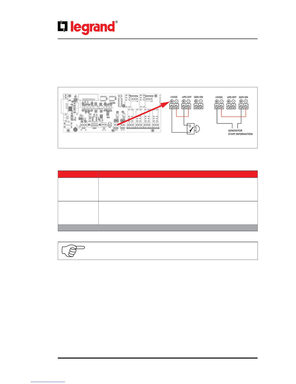
6.3. Emergency Switching Device and Generator Connections
Voltage to be applied to the digital inputs is 5VDC. Maximum current drawn by each input is 1mA. 5VDC
supply provided on the communication interface board can be used to supply both digital inputs.
Figure.8.3-1
UPS output can be switched o immediately by Remote Emergency Switching Device interface (ESD)
connection if desired. A remote latched switch can be used as described in above gure.
Pay attention to the polarity of the voltages applied to the digital input terminals.
Input Function
UPS OFF
If the UPS OFF input is set high by applying 5VDC voltage on the related terminals,
UPS stops generating the output voltage and stops feeding the load. When the
voltage on the digital input is removed, you have to restart UPS. The factory default
setting of ESD contact is “Normally open”.
GEN ON
If the GEN ON input is set high by applying 5VDC voltage on the related terminals,
UPS transfers to Generator Mode, bypass and battery charging is disabled. Gen-
erator icon appears on Energy Flow Diagram screen. The factory default setting of
Generator contact is “Normally open”.
Table.10

 Loading...