Do you have a question about the LEGRAND KEOR T and is the answer not in the manual?
Instructions to read the manual fully before operating the equipment for safety and correct usage.
Advice to store the manual in the UPS front cover for easy access and reference.
Copyright notice regarding manual reproduction, adaptation, or translation.
Manufacturer's right to change technical specifications and design without prior notice.
Instruction to visit the website for the latest manual releases and translations.
Information about CE marking compliance with EN standards.
Explains symbols used in the manual indicating importance, electric shock risk, and injury risk.
Lists and defines abbreviations used throughout the guide for technical terms and functions.
General warning section highlighting critical safety information before installation.
Crucial instruction to consult the installation manual before making any connections.
Warning about high leakage current and the need to connect protective earth.
Warning about the risk of backfeed voltage and the need to isolate the UPS before working.
Safety instruction to wait for capacitor discharge before servicing to prevent electrical shock.
Warning regarding battery circuit breaker usage and fuse replacement procedures.
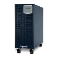
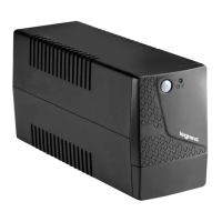
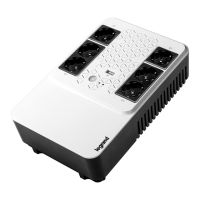
Introduces the KEOR T UPS product, its design philosophy, and key features for high availability and performance.
Defines the manual's purpose, target audience, and scope, excluding maintenance details.
Specifies that only manufacturer-approved configurations and uses are allowed for the equipment.
Emphasizes user's responsibility to adhere to local laws and regulations during equipment operation.
Instruction to retain the manual throughout the equipment's life cycle and obtain replacements if damaged.
Guidance on referring to rating plate data and notifying manufacturer of equipment sale.
Defines warranty coverage by Legrand, including repairs for component, manufacturing, or installation issues.
Lists conditions under which the warranty is void, including improper installation, misuse, and unauthorized modifications.
Explains safety symbols found on the UPS labels, such as Protective Earth, Protective Bonding, and High Voltage warnings.
Details essential personal protective equipment (PPE) required for installation and maintenance due to electrical risks.
Lists specific PPE requirements: safety footwear, rubber gloves, protective gear, and glasses.
Crucial instructions for UPS installation, transportation, placement, grounding, environmental conditions, and connections.
Critical safety information regarding battery installation, handling, disposal, and precautions against shock and fire.
General information on first aid and fire prevention measures for UPS emergencies.
Guidelines for safely transporting the UPS, emphasizing vertical positioning, proper handling, and packaging.
Requirements for installing the UPS in a suitable location, including access, environment, ventilation, and avoiding heat sources.
Instructions for storing the UPS, including temperature, humidity, and periodic battery charging requirements.
Details electrical requirements for installation, including compliance with regulations and dual input considerations.
General instructions for checking the UPS upon delivery and ensuring all components are present before installation.
Provides a detailed list of UPS models, their dimensions, net weight, and internal battery configurations.
Lists available accessories for the KEOR T UPS, such as battery drawer kits and cable kits.
Explains the naming convention used for KEOR T UPS models, including height and battery configuration details.
Step-by-step guide on how to safely unpack the UPS unit and prepare it for installation.
Emphasizes that installation and commissioning must be performed by authorized personnel only.
Advises waiting for two hours before powering the UPS if it has been moved from a cold to a warm environment to prevent condensation.
Recommends protection against voltage surges using suitable devices, limiting surges to 2kV.
Instructions regarding neutral connection to protective ground and the use of isolation transformers if needed.
Critical safety step to ensure all circuit breakers are OFF before beginning power connections.
Describes accessing terminals and routing cables through the UPS unit for power connections.
Diagram illustrating the circuit breaker layout for 10-30kVA 3-phase input/output UPS units.
Identifies key circuit breakers and fuses (Q1, Q2, Q3, Q4, F5, Q6) by their function.
Diagram showing terminal connections for common mains and auxiliary supply when connected together.
Identifies main supply, output, and external battery terminals.
Diagram showing terminal connections for separate mains and auxiliary supply inputs.
Identifies main supply, auxiliary supply, and external battery terminals.
Diagram showing the circuit breaker layout for 40-60kVA 3-phase input/output UPS units.
Identifies key circuit breakers and fuses (Q1, Q2, Q3, Q4, F5, Q6) by their function.
Diagram showing terminal connections for common mains and auxiliary supply when connected together.
Identifies main supply, output, and external battery terminals.
Diagram showing terminal connections for separate mains and auxiliary supply inputs.
Identifies main supply, auxiliary supply, and external battery terminals.
Instructions for properly grounding the UPS device for safe and reliable operation.
Guidance for connecting the main power supply to the rectifier, emphasizing professional installation.
Recommendation to add a 3-pole MCCB to the distribution panel for UPS auxiliary input.
Requirement to affix warning labels regarding voltage backfeed risk on input isolators.
Severe warning about lethal DC voltage present during external battery connections.
Specific instructions for connecting internal batteries, noting missing terminals and pre-transport unconnected cables.
Provides a wiring diagram for 10-30kVA UPS with one string of 60 batteries (7-9Ah each).
Shows the battery terminal layout on the left and right sides of the UPS or battery cabinet.
Provides a wiring diagram for 10-30kVA UPS with two strings of 60 batteries (7-9Ah each).
Shows battery terminal layout on the left and right sides.
Wiring diagram for 40-60kVA UPS with two strings of 60 batteries (7-9Ah each).
Displays battery terminal configuration on the left and right sides.
Wiring diagram for 40-60kVA UPS with three strings of 60 batteries (7-9Ah each).
Shows battery terminal layout on the left and right sides.
States installer's responsibility to check electrical compatibility and protection for non-manufacturer supplied cabinets.
Specifies connecting grounds, strings, neutral, temperature sensor, and breaker feedback for external batteries.
Crucial reminder to double-check battery polarity and ensure breakers are OFF before output connections.
Specific instructions for connecting phase and neutral cables to the output terminals.
Recommends using separate circuit breakers for each load for short circuit protection and operational continuity.
Instructions for connecting an external maintenance bypass using auxiliary contacts.
Introduces the communication capabilities of the UPS for networking and device integration.
Lists standard and optional communication interfaces available for the UPS, such as RS232, RS485, Modbus, etc.
Critical warning against connecting RS232 or external SNMP to wrong ports, which can cause damage and void warranty.
Details the standard serial communication feature of the UPS using an RS232 interface.
Specifies the DSUB-9 male connector and its pin layout for RS232 communication on the UPS.
Details information available for monitoring via SNMP, including battery status and UPS operating parameters.
Explains the installation and configuration of an internal SNMP card for network monitoring.
Instructions for configuring jumpers (J2-J3) for internal SNMP or RS232/RS485 communication.
Describes how to connect the UPS for remote emergency shutdown (ESD) and generator start control.
Specifies the voltage requirement (5VDC) and emphasizes correct polarity for digital inputs.
Describes the four dry contact sockets available for alarm signaling and their programmability.
Specifies the maximum voltage and current limits for applying to the relay contacts.
Lists the default functions assigned to each of the four relays.
Explains the use of RS485 with MODBUS protocol for industrial automation and BMS integration.
Describes the three pins of the RS485 differential line: A, B, and Middle Pin.
Instructions for configuring the Modbus end jumper (J4) for bus termination.
Lists the different tower models of the UPS, specifying phase configuration and power ratings.
Details the technical specifications related to the rectifier input, including voltage and frequency ranges.
Provides technical specifications for the bypass input, such as nominal voltage and frequency tolerance.
Lists technical specifications for the UPS output, including voltage, frequency, THD, and crest factor.
Specifies the battery type and string configuration, and outlines protection features.
Lists communication interfaces and environmental operating parameters, including temperature, humidity, and altitude limits.
Details physical dimensions, weight, and lists safety, EMC, performance, and design standards the UPS complies with.
Provides a detailed list of Modbus registers, their addresses, coefficients, and data definitions for reading UPS data.
Explains how to read UPS data and send commands using Modbus functions.
Explains how to obtain UPS status information using address 127 and converting the decimal value to binary.
Provides an example of receiving a decimal value from address 127 and interpreting its binary representation for status.
Lists and defines key UPS components like circuit breakers, contactors, and terminals.
Explains the functions of the bypass thyristors, rectifier, inverter, and battery subsystems.
Title indicating the block diagram illustrates separate rectifier and bypass input configurations.
Identifies the auxiliary mains supply, common mains supply, and output terminals in the diagram.
Title indicating the block diagram illustrates common rectifier and bypass input configurations.
Identifies the common mains supply and output terminals in the diagram.
Provides the address for Legrand's World Headquarters and International Department.
Placeholder for installer's stamp and details.