44
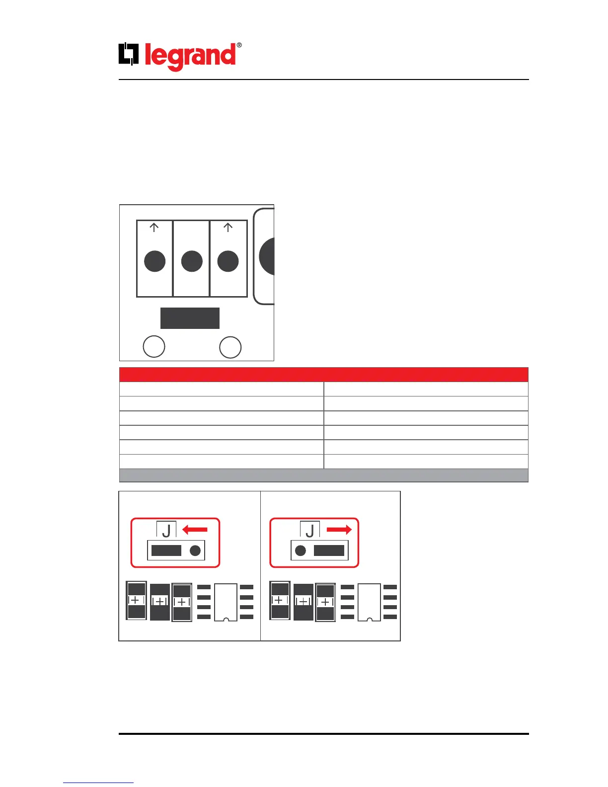
6.5. RS485
RS485 with MODBUS protocol is used in a wide range of automation systems for Industrial Process moni-
toring or for Building Management Systems. This communication link allows monitoring UPS status and
measurements with such systems.
• A is inverting pin (TxD-/RxD-)
• B is non-inverting pin (TxD+/RxD+)
• Middle Pin is reference pin (optional GND)
Middle Pin is the reference potential used by the transceiver
to measure the A and B voltages.
The B line is positive (compared to A) when the line is idle.
The RS485 dierential line consists of three pins:
Modbus End Jumper (J4): If
the UPS is at the end of the bus;
the jumper should be moved to
right side to close the bus.
Communication Parameters
Baud Rate 2400
Data Bits 8
Stop Bits 1
Parity No Parity
Flow Control No Flow Control
Communication Type RTU
Table.13
RS485
RS485
AB
R24
R24
J4 J4
C18
C18
R22
R22
U1_485
•
U1_485
•

 Loading...