2
WARNING: TURN THE POWER OFF AT THE
CIRCUIT BREAKER BEFORE INSTALLING
THE DEVICE OR POWER/SLAVE PACKS.
LOAD TYPES
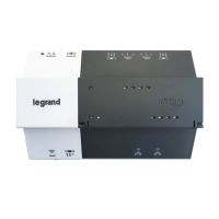
Use the DCLV2 for these load types:
• 0 to 10V electronic dimming ballasts (Mark 7 or equivalent)
with maximum of up to 50mA.
• Compatible LED systems (verify compatibility with LED control
manufacturer).
TERMINAL BLOCK
The DCLV2 has a wiring terminal block with 7 positions:
1 24VDC input
2 Common
3 0–10V Violet
4 Sensor input
5 Control Output
6 0–10V Gray
7 Common
DIMMING MODE
The DCLV2 supports low-voltage DC dimming, using Class 2
wires. Multiple circuits can use the same dimming signal without
additional power equipment.
0–10V Dimming curves
To accommodate various types of ballasts, the DCLV2, executes
a straight proportional relationship between the internal level and
the voltage provided, 0.6VDC to 9.5VDC.
0–10V Dimming (with ON/OFF option)
• When the user ramps up, relay 1 output
switches from 0V to 24VDC. This closes
the power pack relay to supply line
voltage to the light fixtures.
• When the user ramps down and the
0–10V output becomes 0V, relay 1
switches to 0V. This opens the power
pack relay to remove power to the
light fixtures. This allows the ballast to
smoothly ramp down and then be turned
OFF.
NOTE: An ON to OFF transition can take
longer than expected (by about 2
seconds) because the DCLV2 is
dimming down. The OFF to ON
transition is immediate.
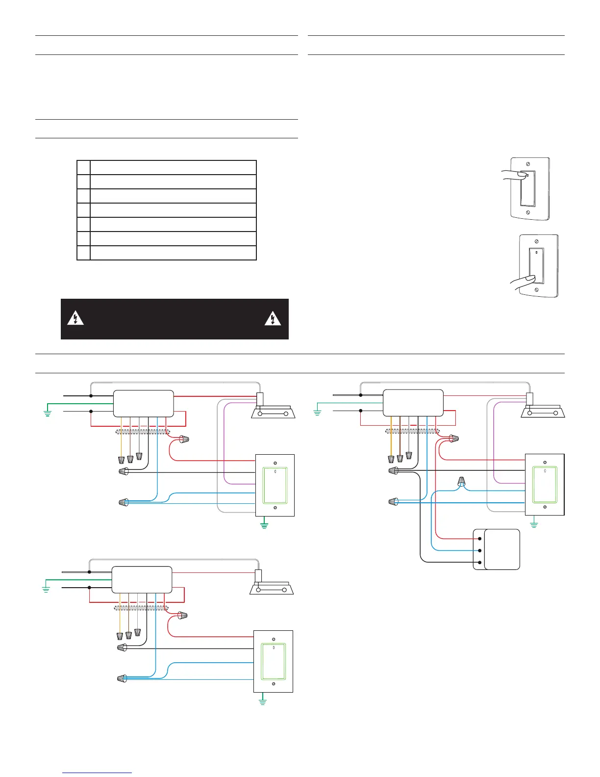
WIRING EXAMPLES, LIGHTING CONTROL
Neutral
Hot
White
Black
Red
Red
Fixture
Red
Black
Blue
Orange
Brown
Gray
Low Voltage Wires
24VDC
0–10V
Control
0–10V
Common
Red
VioletGray
Black
Power Pack
BZ Series
DCLV2
Blue
Sensor
Blue
0-10V wiring diagram
Neutral
Hot
White
Black
Red
Red
Fixture
Sensor
Ceiling/Wall
24VDC
Any
Red
Black
Blue
Orange
Brown
Gray
Low Voltage Wires
24VDC
0–10V
Sensor
Control
0–10V
Ground
Common
Red
VioletGray
Black
Black
Control Output
+24VDC
Red
Common
Power Pack
BZ Series
DCLV2
Blue
Blue
Blue
Sensor input wiring diagram
Ballast ON/OFF control wiring diagram
To control a simple ON/OFF system do not connect the 0-10V output on
the DCLV2.
Neutral
Hot
White
Black
Red
Red
Fixture
Red
Black
Blue
Orange
Brown
Gray
Low Voltage Wires
24VDC
Control
Common
Red
Black
Power Pack
BZ Series
DCLV2
Blue
Sensor
Blue
NOTES
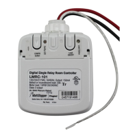
Any BZ series power pack will work with the DCLV2, but the
following should be noted
• The Orange, Brown, and Gray wires on the BZ-150 and
BZ-250 are not used and should be capped
• The Manual/Auto On switch on the BZ-150 and BZ-250
should be left in the Auto-On position. Manual functionality is
handled by the DCLV2.
• The BZ-200 and BZ-250 must be grounded to ensure signal
integrity,not for safety ground.







 To Next Page